
Available direction

Start with the application problem—not a premature component choice

Start with what the application must do, not a prematurely selected component. These five problem routes show which product families to compare and which questions reduce architecture risk first.

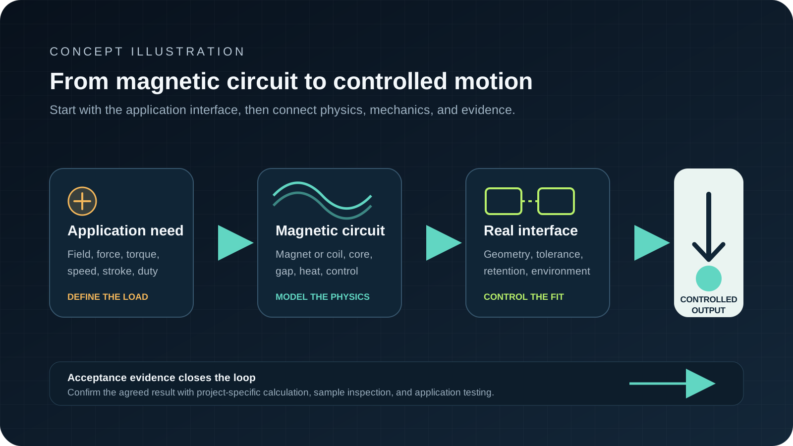
Concept diagram connecting magnetic circuits, electromagnetic conversion, and controlled motionConcept illustration
Original scope illustration. It helps route the engineering problem and does not represent a supplied architecture.
Confirm for your project

Route by state behavior and output

First define what must happen in normal operation, at the critical operating point, and when power is removed. Then connect that behavior to interfaces, environment, control, safety, and the evidence needed for acceptance.

  • Passive, energized, latching, reversible, or controllable state
  • Field, force, torque, speed, stroke, position, or sensing output
  • Air gap, mating structure, supply, driver, feedback, and thermal path
  • Fail state, overload, life, environmental exposure, and test method

Five problem routes

Find the first questions and product families to compare

Route 1

Magnetic Holding and Positioning

Hold, locate, couple, release, or index a part while balancing useful force, air gap, safety, surface protection, space, and energy use.

Decision boundary: Start with the required state behavior and force at the real working gap. That separates passive permanent-magnet concepts from energized electromagnets, latching devices, and integrated magnetic assemblies.

Questions to close first

  1. 1What must happen when electrical power is removed?
  2. 2What holding or release force is required at each real air gap?
  3. 3What are the target material, surface, geometry, alignment, and allowed contact pressure?
  4. 4Which temperature, corrosion, contamination, shock, and safety conditions apply?

Compare these families

Route 2

Rotational Motion

Convert electrical input into controlled rotary output inside limits for torque, speed, duty, temperature, acoustics, package, feedback, and transmission.

Decision boundary: Define the complete operating points and motion cycle before selecting a motor technology. The useful comparison is at the shaft and application duty, not by motor diameter or nominal power alone.

Questions to close first

  1. 1What continuous, peak, starting, and holding torque is needed at each speed?
  2. 2What is the real move, dwell, reverse, start-stop, and overload sequence?
  3. 3What supply, driver, control, feedback, transmission, and load inertia are fixed?
  4. 4What envelope, mounting, shaft, thermal path, noise, life, and environment limits apply?

Compare these families

Route 3

Linear Actuation

Create a pull, push, hold, latch, release, or positioned linear movement with a defined force-stroke-time profile and fail state.

Decision boundary: Route short-stroke electromagnetic actions toward solenoids and coils, and route longer or controlled motion toward a motor-plus-transmission concept. Compare the complete force, speed, duty, and life requirement.

Questions to close first

  1. 1What force is required at the start, intermediate, and end of stroke?
  2. 2What travel, speed, response, repeatability, and fail position are required?
  3. 3What is the exact energization or motion cycle and expected life?
  4. 4What supply, driver, package, guides, load, temperature, and contamination conditions apply?

Compare these families

Route 4

Sensing and Field Control

Create a usable magnetic field for sensing, switching, biasing, calibration, attraction, or controlled field exposure while managing geometry, variation, temperature, and interference.

Decision boundary: Define the field objective at a coordinate or measurement volume, including direction and tolerance. Then compare a permanent source, a driven coil, or an assembly that combines flux guidance and mechanical datum control.

Questions to close first

  1. 1What field, gradient, switching threshold, or sensor output is required and where is it measured?
  2. 2What air gap, motion, alignment, nearby steel, and assembly variation affect the field?
  3. 3Must the field be passive, switched, reversible, adjustable, or de-energized to a safe state?
  4. 4What temperature, aging, interference, shielding, calibration, and validation conditions apply?

Compare these families

Route 5

Integrated Magnetic and Motion Subassemblies

Combine magnetic, electromechanical, structural, electrical, and mating functions into a controlled subassembly instead of sourcing disconnected parts.

Decision boundary: Freeze functional interfaces and acceptance evidence before optimizing parts. The review should own the tolerance stack, magnetic or motion performance, retention, thermal path, electrical connection, revision boundary, and application test.

Questions to close first

  1. 1Which functions and interfaces should be controlled at subassembly level?
  2. 2Which dimensions, performance outputs, materials, and records are critical to quality?
  3. 3Who owns the mating parts, electronics, fixtures, system validation, and change approval?
  4. 4What prototype stages, acceptance tests, packaging, traceability, and delivery conditions are needed?

Compare these families

Confirm for your project

Describe the problem if the component architecture is still open

Share the required state behavior, output, interfaces, environment, duty, fail condition, validation evidence, quantity, timing, and destination. The review can compare product-family routes without treating them as confirmed availability.

An initial review identifies missing inputs and next steps. It does not by itself confirm feasibility, performance, price, or delivery timing.