Semiconductor handling · Vacuum chambers · Positioning mechanisms
Vacuum motion integration
Define the chamber boundary before selecting the drive. Magatom helps OEM teams compare drive placement, preparation, heat paths and feedthrough interfaces for vacuum positioning and semiconductor handling.
Magatom Dynamics · Application engineering guide · Reviewed
Start with the mechanism and its assembly boundary
A wafer-handling or chamber-positioning task starts with a process boundary. Identify what moves inside the chamber, which components can stay outside and how motion, power and feedback cross the wall. This architecture decision can change the parts exposed to vacuum and the interfaces that need preparation or evaluation.
Write the pressure, process exposure and contamination objective alongside the motion cycle. Keep operating temperature and bakeout conditions separate. A material name or an ambient-air motion test leaves important questions open about the assembled mechanism, its preparation and the conditions under which it will operate.
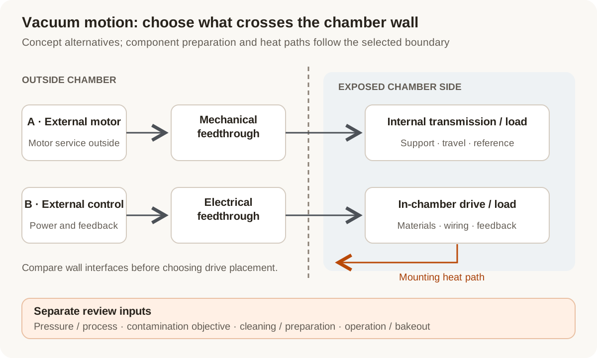
Concept architecture comparison: an external drive crosses a mechanical boundary; an in-chamber drive adds electrical, material and thermal interfaces inside the chamber.
Original Magatom application-engineering diagram. Scroll horizontally to inspect the diagram labels.
Compare drive placement at the vacuum boundary
Choose the layout around the process, required travel and available wall interfaces. Each option moves a different set of components and preparation decisions into the chamber.
| Architecture | When to compare | Interfaces to review |
|---|---|---|
| External drive with mechanical feedthrough | Compare when motion can be transmitted through a suitable wall interface while the motor and service connections remain outside. | Define the feedthrough, shaft/coupling support, alignment, travel and internal transmission. Include the chamber-side loads and measurement reference. |
| In-chamber drive and mechanism | Compare when the package or motion task calls for the drive to be located with the moving mechanism. | Review all exposed materials, lubrication, wiring, feedback, heat paths and preparation. Define electrical feedthroughs and access for installation. |
| Split drive or isolated transmission interface | Compare when only part of the drive chain can be exposed and a separated layout is useful for the chamber geometry. | Draw the exact vacuum boundary and identify the components on each side. Review any coupling or isolation barrier for its own loads, clearances and integration work. |
Turn a vacuum label into preparation and operating inputs
Treat the chamber and its assembled motion path as the review unit. The following decisions connect component selection to a usable process brief.
Pressure and process contamination
State the pressure at which motion is required, the pump-down objective and the process exposure. Identify sensitive surfaces and permissible particles or residual species. A pressure target and a cleanliness objective are separate acceptance inputs.
Materials, lubrication and preparation history
List exposed parts, lubricants, insulation, adhesives and surface treatments. Record cleaning, cure, handling and packaging requirements with the selected revision. Read outgassing data with its specimen and test preparation rather than treating a material-family name as assembly evidence.
Operating heat and bakeout conditions
Specify the motion duty and permissible temperatures during operation, then separately define bakeout temperature, duration and component removal needs. Review conduction to the structure and other available heat-transfer paths at the requested pressure.
Feedthroughs, feedback and mounting access
Map power, feedback and motion through the chamber wall. Review connector pinout, cable movement, trapped volumes, mounting datums and installation access. Include the measuring reference and service plan when choosing which components remain inside.
Prepare the load, environment and interface brief
Send the values you know and identify the open choices. These are application inputs for review; keep the requested targets separate from the specifications of any selected component.
| Input | What to send | Decision it supports |
|---|---|---|
| Chamber and drive placement | Boundary sketch, available ports, internal envelope and candidate drive location. | Establishes what is exposed and which interfaces cross the wall. |
| Process and pressure | Working pressure, pump-down objective, process gases and exposure sequence. | Defines the actual environment of the moving components. |
| Contamination objective | Particle, residual-gas or sensitive-surface requirements and measurement method. | Sets preparation and evaluation criteria separately from pressure. |
| Motion and payload | Travel, speed, cycle, payload, support loads and positioning reference. | Connects the handling task to transmission and mounting requirements. |
| Materials and preparation | Permitted materials/lubricants, cleaning, cure, handling and packaging records needed. | Defines the configuration and process history to review. |
| Thermal conditions | Operating duty, mounting heat path, temperature limits and separate bakeout sequence. | Keeps operating thermal behavior distinct from preparation exposure. |
| Wall and signal interfaces | Mechanical/electrical feedthroughs, feedback, pinouts, cable travel and access. | Connects the complete mechanism to the chamber and controller. |
| Evaluation and project stage | Agreed chamber setup, observation records, prototype quantity and revision stage. | Defines the next build and configuration-linked evaluation. |
Plan the prototype observations and next revision
01
Freeze the exposed configuration
Agree the boundary drawing, parts/materials list, preparation sequence, feedthroughs and mounting before the prototype build.
Planned output: A revision-controlled exposed-assembly and interface brief.
02
Agree the chamber observation plan
Define the pressure/process setup, preparation, motion duty, temperatures and requested contamination or positioning observations with the chamber team.
Planned output: An evaluation plan linking each observation to the configuration and operating conditions.
03
Review changes before the next build
Compare the agreed observations and inspect installation/service issues. Identify which material, lubricant, cable or geometry changes need another review.
Planned output: A documented next revision and preparation/acceptance inputs for repeat builds.
Shape the assembly-development scope
- An in-chamber versus external-drive architecture comparison for the actual mechanism.
- Defined mounting, transmission, feedthrough, preparation and feedback interfaces.
- A prototype plan tying motion and environment observations to the chosen assembly revision.
Questions about vacuum motion integration
Should the motor be inside or outside the vacuum chamber?
Compare the required motion, available ports, internal envelope, preparation and thermal requirements. An external motor leaves a mechanical wall interface to develop; an in-chamber motor brings its exposed materials, electrical connections and heat paths into the assembly review.
Does a low-outgassing material establish vacuum compatibility?
Use material data with its preparation and test conditions as one input. Review the full exposed parts list, lubricants, wiring, process exposure and assembly preparation against the chamber’s actual pressure and contamination objectives.
Are bakeout and operating temperature the same requirement?
No. Record the bakeout sequence, temperature and duration separately from powered operation, motion duty and mounting heat paths. State which components remain installed during preparation so both conditions can be reviewed.
Can semiconductor handling and general vacuum positioning share one specification?
They may share mechanical ideas, but their process and contamination requirements can differ. Define the actual chamber exposure, sensitive surfaces, pressure, particles and residual species before carrying a preparation or component choice between applications.
Can we retain our existing feedthrough and controller?
Yes. Supply their drawings, travel/load limits, pinouts, signals and available mounting space. Treat them as fixed interfaces and identify the drive, support, coupling or cable work still needed around them.
What should the first vacuum motion evaluation record?
Agree the assembly revision, preparation and chamber setup first. Then define the motion, temperature, pressure and contamination or positioning observations needed for the project. Keep the records tied to those conditions when deciding the next revision.
Connect the brief to component and project information
Technical reading behind the interface decisions
- Physik Instrumente: Positioning in high vacuum and ultrahigh vacuum
In-chamber and external-drive examples; material preparation, feedthroughs, bakeout and configuration-specific vacuum evaluation.
- NASA: Outgassing test and data description
How preparation and test conditions affect interpretation of material data.
Application & assembly review
Draw the chamber boundary before selecting the drive
Send a chamber sketch, motion cycle, pressure/process conditions, preparation requirements and existing feedthroughs. We can compare the drive placement and define the open assembly interfaces.
Bring a sketch, selected components or the open interface questions. Use the review to define the assembly scope and next development step.