Force-stroke and electromagnetic actuation review

Custom Electromagnets, Solenoids, and Coils

This path is for OEM teams that need electrically controlled holding, pulling, pushing, latching, proportional force, or a custom coil. Begin with force at each critical stroke position and the time/energy sequence, then close supply limits, duty, return mechanism, thermal path, envelope, environment, life, interfaces, and a repeatable acceptance test.

Best starting point

Equipment teams designing electrical holding, locking, valve, switching, braking, release, push-pull, or proportional actuation functions.

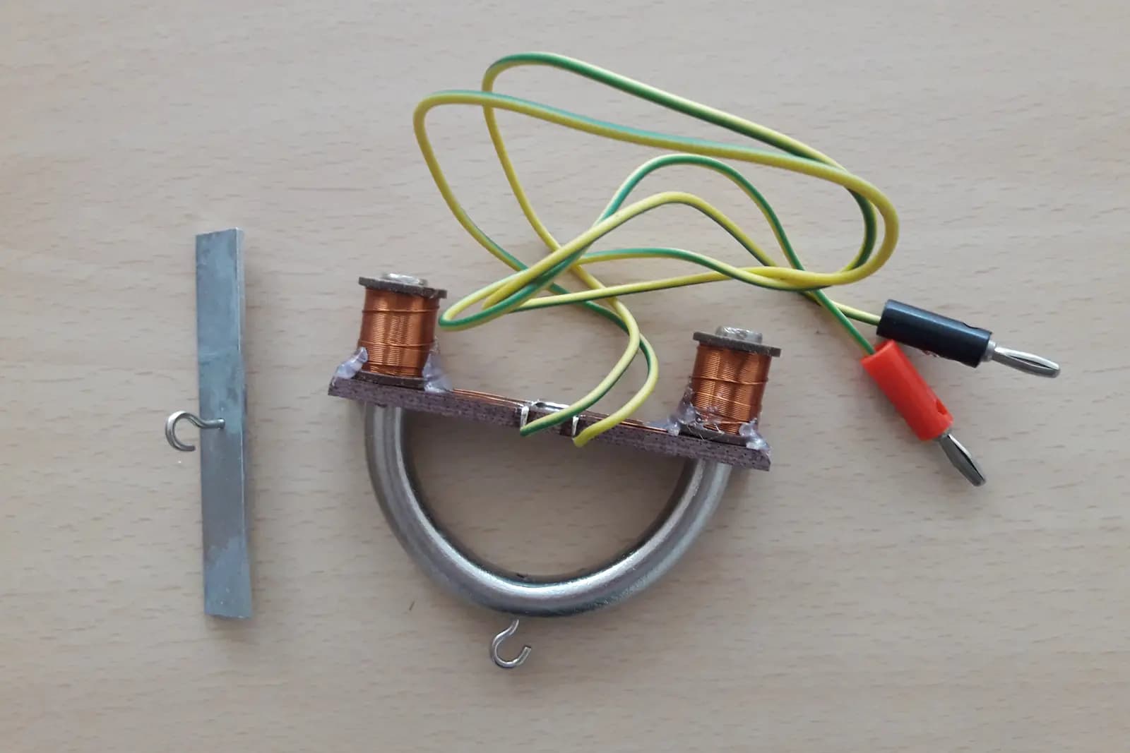
Representative open-core electromagnet demonstrator with two copper coils and test leadsRepresentative visual

Representative category visual; force-stroke behavior, winding, duty, interfaces, and protection are confirmed for each project.

Photo by Zheludenko Pavlo, resized and cropped from the original. Source · CC BY 4.0

Capability-domain role

Electromagnetic Conversion & Actuation →

Also interfaces with Precision Motion & Integrated Modules.

Electromagnets and solenoids convert electrical input into controlled force or motion and frequently integrate with valves, locks, brakes, and mechanisms. Exact architecture, manufacturing route, validation evidence, and supply commitment remain project-specific.

Available direction

What this review covers

  • Requirement review for holding electromagnets, linear/tubular/rotary/latching/proportional solenoids, valve coils, brakes, clutches, locks, and wound components
  • Review of magnetic circuit, winding, force-stroke behavior, return, thermal duty, electrical protection, mechanics, and interfaces
  • Prototype acceptance planning for force, stroke, response, current, temperature, insulation, noise, leakage, or cycle behavior as applicable
Confirm for your project

What is not pre-confirmed

  • A guaranteed force, duty, temperature, response, life, IP rating, or safety function before conditions and validation are agreed
  • A complete valve, lock, brake, or certified machine-safety subsystem unless its wider interfaces and compliance ownership are in scope
  • Unverified stock, tooling, certification, factory, or volume capability claims
Available direction

Application routes

Use these routes to describe the function. Final architecture and component choices follow the operating conditions and interfaces.

Holding, release, and locking

Where energized/de-energized state, residual force, target material, gap, fail position, and release time matter.

Valve and fluid actuation

Where force-stroke, pressure/load, response, sealing boundary, contamination, coil temperature, and duty interact.

Push-pull and indexing mechanisms

Where moving mass, spring/load curve, impact, side load, travel, rate, noise, and cycle life shape the design.

Proportional force or custom coils

Where current-force behavior, hysteresis, sensor/control context, winding space, insulation, and thermal path must be reviewed.

Confirm for your project

Engineering inputs that shape the decision

Items marked required are needed to close the basic requirement. Optional choices may remain open for the review.

Force over stroke

Required input

Give required pull/push/hold force at start, intermediate, and end positions plus the external load or pressure curve.

Why it matters: Solenoid force changes strongly with air gap; a single force number is ambiguous.

Duty and energization profile

Required input

State on/off time, cycles per minute/hour, hold duration, simultaneous coils, stall condition, and worst repetition.

Why it matters: Copper temperature and achievable force depend on time, not voltage alone.

Voltage and current

Required input

Provide supply range, current limit, driver type, PWM or overdrive/hold strategy, polarity, suppression, and power tolerance.

Why it matters: Drive strategy changes pull-in force, response, heating, release time, and insulation stress.

Response and motion

Required input

Define energize-to-motion, full travel, holding, release, bounce, impact, speed, and acceptable noise behavior.

Why it matters: Response depends on electrical, magnetic, mechanical, load, friction, and suppression choices.

Envelope and stroke

Required input

Provide available body/coil/plunger space, mounting, travel, air gaps, alignment, leads/connector, and service constraints.

Why it matters: Envelope and stroke set magnetic circuit and winding trade-offs.

Return and fail state

Required input

Define spring, gravity, external load, permanent-magnet latching, bistable state, or powered return and the required power-loss behavior.

Why it matters: Return architecture affects force budget, residual behavior, safety, energy, and response.

Thermal limits

Required input

State ambient, mounting heat path, airflow, nearby heat, allowable coil/body temperature, insulation class requirement, and measurement point.

Why it matters: Temperature rise limits continuous force and affects resistance, insulation, and life.

Environment

Required input

Describe fluids, dust, moisture, vacuum, corrosion, pressure boundary, washdown, vibration, shock, EMC, and cleanliness.

Why it matters: Protection and materials must match the actual exposure and moving interface.

Life expectation

Required input

Provide cycles or hours, load distribution, impact/landing behavior, maintenance, wear parts, and acceptable drift.

Why it matters: Mechanical wear, spring change, impact, insulation aging, and contamination can govern life.

Available direction

Options to compare—not catalog promises

These are review directions. Availability, process route, evidence, and commercial terms remain project-specific.

Actuation architecture

Linear pull/push solenoid

Compare force-stroke curve, moving mass, return load, side load, end impact, duty, and package.

Holding electromagnet

Compare target material, contact/gap, residual/release behavior, duty, surface condition, and power-loss state.

Latching or bistable solenoid

Compare pulse energy, two-state force margins, polarity/control, shock, release method, and position evidence.

Proportional or rotary architecture

Compare useful range, linearity, hysteresis, bearing/friction, feedback/control, heat, and calibration needs.

Winding and drive strategy

Continuous or intermittent winding

Select from thermal duty and force needs, not from supply voltage alone.

Pull-in/hold current control

Evaluate when high initial force and lower steady heating are needed; confirm driver and fault behavior.

Suppression and release tuning

Choose diode, TVS, resistor, active clamp, or other protection only after release time, voltage stress, and EMC are reviewed.

Confirm for your project

Evaluation matrix

Compare candidate directions using application conditions and request evidence tied to a defined revision and test method.

Evaluation criteria and evidence to request for Custom Electromagnets, Solenoids, and Coils
CriterionWhat to compareEvidence to request
Force-stroke marginAvailable force against external load, friction, spring, pressure, orientation, voltage tolerance, temperature, and wear at every critical position.Force-stroke test conditions and sample results over agreed voltage and temperature cases.
Thermal dutyCoil/body temperature at worst energization sequence, ambient, mounting, airflow, resistance, and driver behavior.Duty trace, temperature points/limits, stabilization rule, and insulation requirements.
Response and releaseElectrical time constant, drive/suppression, magnetic gap, moving mass, return load, friction, residual force, and landing.Defined timing references and response test under the representative load.
Life and environmentImpact, guides/bearings, spring, contamination, corrosion, fluids, insulation, leads/connectors, and cycle distribution.Relevant conditioning and cycle plan with failure criteria and inspection intervals.
Confirm for your project

Validation path

A useful result records the conditions, revision, method, output, deviations, and acceptance decision.

  1. Stage 1

    Function definition

    Map force versus stroke and time, external load, fail state, supply/driver, duty, thermal path, and environment.

    Review output: Reviewed actuator requirement and open-decision list.

  2. Stage 2

    Bench characterization

    Measure force-stroke, current/resistance, travel, pull-in/hold/release, response, noise, and temperature under defined conditions.

    Review output: Condition-specific prototype results tied to revision.

  3. Stage 3

    Application cycling

    Run representative load, mounting, drive, environment, and duty through an agreed cycle or endurance sequence.

    Review output: Wear/temperature/function observations and acceptance decision.

  4. Stage 4

    Release control

    Freeze winding, insulation, mechanics, interfaces, driver assumptions, tests, markings, and packaging requirements.

    Review output: Revision-controlled supply requirements subject to confirmation.

Confirm for your project

Risk and control matrix

Project risks and controls for Custom Electromagnets, Solenoids, and Coils
RiskConsequenceControl
Force specified at only one positionThe actuator may hold at end stroke but fail to start motion at the largest gap.Define the load and required margin across the full critical stroke.
Duty stated as a percentage onlyDifferent cycle periods can create different thermal peaks and cooling time.Provide the exact on/off sequence, repetitions, ambient, mounting, and worst fault state.
Suppression slows releaseA protective diode or driver strategy may delay current decay and mechanical release.Validate the complete drive, clamp voltage, timing, load, and fail behavior.
Side load or contamination increases frictionForce margin, response, wear, and life can degrade in the application.Define alignment, guides, seals, particles/fluids, orientation, and application-level cycling.
Confirm for your project

RFQ checklist

  1. 1Force required at each critical stroke position plus external load/pressure/friction assumptions
  2. 2Travel, air gap, envelope, mounting, alignment, leads/connector, and mating interfaces
  3. 3Supply range, current limits, driver/PWM/overdrive strategy, suppression, and fault behavior
  4. 4Exact energization sequence, cycle rate, hold time, simultaneous operation, and stall condition
  5. 5Return mechanism, fail state, residual/release requirement, orientation, and impact/noise limits
  6. 6Ambient, thermal path, coil/body temperature limits, environment, ingress, fluids, and vibration
  7. 7Life target, maintenance, validation sequence, insulation/electrical tests, and documentation needs
  8. 8Project stage, sample quantity, estimated demand, destination, and target timing

Buyer FAQ

Why is force required at several stroke positions?

Electromagnetic force changes with air gap. A device that meets force near the end position may not overcome the load, spring, friction, or pressure at the start of travel.

Is duty cycle percentage enough?

No. Provide actual on/off duration, repetitions, ambient, mounting/cooling, voltage/current strategy, and the worst fault or stalled condition. The same percentage can produce different temperature peaks.

Can I request a solenoid without selecting a construction?

Yes. Define force-stroke-time behavior, supply/driver, package, return/fail state, thermal limits, environment, life, and acceptance. Construction can remain open for review.

Are listed solenoid and coil types standard products?

They are evaluation directions. Final architecture, performance, protection, documentation, tooling, quantity, supplier route, and timing are confirmed for the project.

Continue the decision

Confirm for your project

Define force over stroke and time before choosing the actuator

Share force at critical positions, the external load, drive/supply, exact duty, return/fail state, package, thermal limits, environment, life, and acceptance method.

An initial review identifies missing inputs and next steps. It does not by itself confirm feasibility, performance, price, or delivery timing.