Request a Sensor
Bring a model or measured-load requirement for component selection and supply.
Request a Sensor →Load cells · Torque · Multi-axis sensing · Readout kits
Measure the force or torque that matters to your machine. Compare load cells, torque sensors and multi-axis sensing, then define the mounting, signal chain and acceptance records with Magatom. Start with a sensor requirement or bring an existing model and the interface changes you need.
Best starting point
OEM mechanical, test and automation engineers and procurement teams matching a measurable load to a sensor and readout configuration.
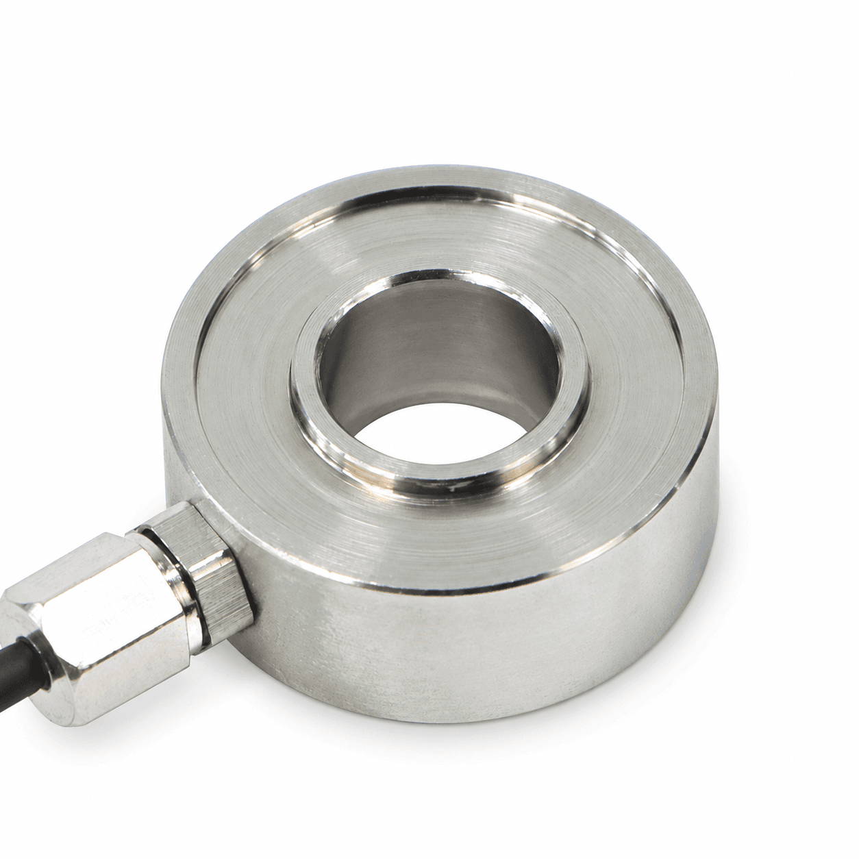
Through-hole compression load-cell form: review the loading face, bore and cable clearance.
Supplier-derived product-form reference from the owner’s sensor image library.
Capability-domain role
Also interfaces with Motion Assemblies & Interface Integration.
Force and torque feedback connect machine loads to the motion, test and mechanical interfaces already reviewed for OEM assemblies.
Bring a model or measured-load requirement for component selection and supply.
Request a Sensor →Define the sensor, cable, readout and configuration or calibration records together.
Specify a Matched Kit →Agree the mounting or electrical changes, sample scope and acceptance work.
Discuss Interface Customization →Compare the component forms and interface concepts below when preparing your assembly brief.
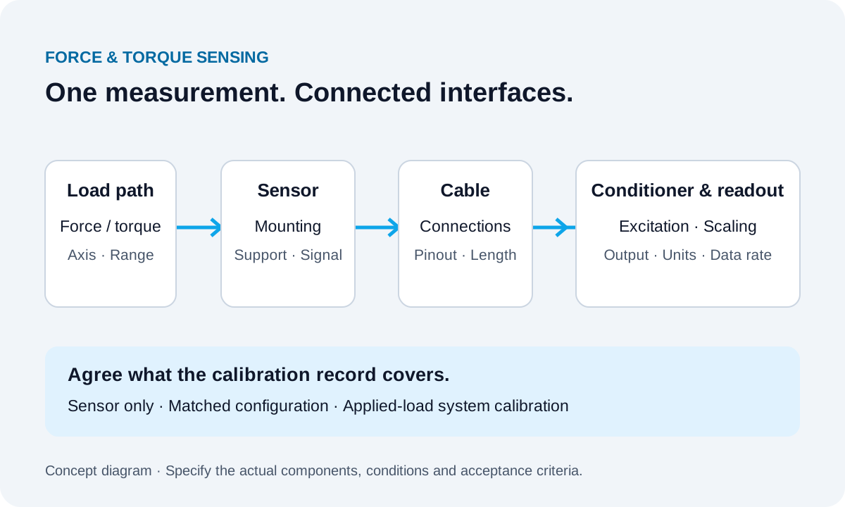
Measurement-chain concept: define each interface and the configuration covered by the calibration record.
Original Magatom editorial artwork.
Connect the equipment function to its load, mounting, magnetic circuit or electrical interfaces. Use these examples to frame the design questions for your project.
Measure axial compression or tension while controlling mounting preload, alignment and overload exposure.
Review the bore, annular contact area, body height and force path around the existing fastener or shaft.
Distinguish stationary reaction torque from a rotating shaft measurement, then define the speed, mounting and signal path.
Specify the required force/moment components, coordinate frame, combined loading and data interface before selecting the configuration.
Items marked required are needed to close the basic requirement. Optional choices may remain open for the review.
Force or torque; tension/compression, clockwise/counter-clockwise, or the required Fx/Fy/Fz/Mx/My/Mz components.
Why it matters: A through-hole load cell, a joint torque ring and a six-axis sensor measure different quantities.
Normal minimum/maximum, transient peaks, preload, load reversals and overload cases, with units.
Why it matters: The working measurement range and survival/overload limits are different selection criteria.
Sketch the applied load, reaction structure, contact faces, threads or bolt circle and any side loads.
Why it matters: Fixture alignment, mounting preload and unintended bypass paths affect what reaches the sensor.
Bore, outside dimensions, height, mating tolerances, cable exit and connector/service clearance.
Why it matters: Similar appearance or outside diameter does not establish an interchangeable mechanical interface.
Accuracy objective, repeatability, sampling/bandwidth needs, filtering, response time and the condition where each is evaluated.
Why it matters: Resolution, nonlinearity, repeatability and assembled-system uncertainty are different quantities.
Available supply, mV/V bridge input or required analog/digital output, controller/readout model and cable length.
Why it matters: The bridge, conditioner, cable and receiving device need a compatible electrical and scaling arrangement.
Temperature range, moisture, cable motion, vibration, duty, fatigue cycles and maintenance needs.
Why it matters: The installation conditions influence sensor construction and the validation boundary.
Sensor only or a matched kit, calibration directions/range, required records, sample quantity and production plan.
Why it matters: A component certificate and an applied-load system calibration cover different delivery configurations.
Technical references
Use these references to compare engineering methods and selection criteria. Product ratings belong to the specific configuration and operating conditions being quoted.
Distinguishes sensor calibration from the sensor, cable and electronics measurement chain.
Explains mechanical installation, electrical chain and calibration methods.
Discusses measurement quantities, performance and matched configuration records.
Compare the alternatives against your fixed interfaces and operating conditions, then agree the selected configuration and production route.
Compare button, through-hole, inline and other forms against loading direction, contact geometry and the available envelope.
Specify stationary reaction or rotating-shaft torque; a hollow passage alone does not make a force washer a torque sensor.
Define the required components, coordinate frame, combined-load envelope, calibration matrix and data rate for review.
Match excitation, bridge sensitivity, channels, output range/protocol, scaling, cable and receiving instrument.
Start with a sensor model or requirement and define its drawing, electrical interface and calibration/documentation scope.
Specify the sensor, cable and electronics together. Agree configuration, scaling and the calibration record covering the delivered set.
Define mounting, cable, connector or other required changes, then agree design outputs, samples and acceptance tests.
Compare candidate directions using application conditions and request evidence tied to a defined revision and test method.
| Criterion | What to compare | Evidence to request |
|---|---|---|
| Load direction and mechanical path | Loading face/thread/flange, support, preload, off-axis exposure and protection. | Selected drawing, mounting instructions and the application load sketch. |
| Measurement range and performance | Working and combined loads, overload, nonlinearity, repeatability, noise and dynamic behavior. | Configuration-specific specification and test/calibration conditions, including units and axes. |
| Electrical chain | Supply/excitation, bridge sensitivity, output type, scaling, connectors, cable and receiver. | Wiring/pinout, conditioner configuration, interface documentation and included accessories. |
| Calibration boundary | Sensor-only calibration, electronics setup and applied-load system calibration for the delivered arrangement. | Record identifying the sensor, electronics, cable/configuration, load directions, range and results. |
| Supply and change control | Sample configuration, quantity, drawing revision, expected production plan and replacement parts. | Agreed quotation, revision and acceptance/documentation requirements. |
A useful result records the conditions, revision, method, output, deviations, and acceptance decision.
Confirm units, directions, working/peak loads, fixture and the required observable output.
Review output: A sensor brief and fixed/open interface list.
Compare drawing, electrical interfaces, excitation, cable, output/scaling and readout settings.
Review output: A named sensor/electronics/accessory configuration and acceptance plan.
Specify load directions/range and whether acceptance covers a sensor or the complete measurement chain.
Review output: Applicable calibration and configuration records, with actual results distinguished from targets.
Review installation readings and agreed application tests, then approve the revision and production documents.
Review output: An accepted sample configuration and repeat-supply/change-control scope.
Share the operating points, interfaces, environment, and acceptance method that matter most. The first review can identify missing inputs before a configuration or production route is assumed.
| Risk | Consequence | Control |
|---|---|---|
| Force does not pass through the intended sensing axis | The reading may not represent the application load. | Review mounting faces, alignment, reaction support and possible bypass paths before sizing the sensor. |
| Conditioner pairing is treated as system calibration | Configured scaling alone may not establish the required measurement accuracy. | Name the delivered sensor/cable/electronics and agree the calibration method and records. |
| A signal or communication label hides interface details | The receiving device may interpret the output incorrectly. | Verify supply, pinout, protocol/data format, units, scaling, rate and required software configuration. |
| An actuator and torque sensor are combined by dimensions alone | Mounting, support or the load path can bypass or overload the sensor. | Review the complete mechanical stack and measurement purpose as a defined integration project. |
Start with the measured quantity and load path. Define axial force, stationary reaction torque, rotating torque or multiple force/moment components, then compare the mounting, range and signal chain. A sketch and known operating loads are enough to begin.
Yes. Describe the sensor input, desired output, receiving device and cable requirements. We review a matched configuration and agree the setup and calibration records for the supplied arrangement.
Electrical matching and scaling are different from applied-load system calibration. Specify whether you need sensor-only records or calibration of the sensor, cable and electronics together; the quotation identifies the included configuration and records.
No. A through-hole load cell can measure axial force around a passage, while a torque sensor measures a twisting moment. Confirm the measured directions, loading faces and mounting arrangement rather than selecting by the central hole alone.
Send the reference specification and drawing, installed load, wiring, excitation, readout and the reason for the change. Compare mechanical and electrical interfaces, measurement requirements and calibration scaling before agreeing candidate samples.
Bring the actuator and sensor references, mechanical stack, bearing support and required measured torque. We review these as an integration project so mounting, load path, feedback and acceptance are defined together.
Identify the required bridge, analog or digital interface and your receiving device. Options such as mV/V, voltage/current or digital communication depend on the selected sensor and conditioner configuration; specify the units, scaling, channel count and rate as well.
No. Share the function, known loads, available space and open questions. Use the form for the first brief and send drawings or reference specifications by email afterward. Sample quantities, timing and development work are agreed after the configuration review.
Application & assembly review
Bring the measured load, mounting envelope and desired signal output. Include an existing sensor or readout reference and choose component supply, a matched kit or a defined development project.
Bring a sketch, selected components or the open interface questions. Use the review to define the assembly scope and next development step.