Magnetic circuit and mechanical integration review

Custom Magnetic Assemblies

This path is for OEM teams that need a magnet integrated with steel, polymer, adhesive, shaft, hub, housing, or another functional interface. Begin with the magnetic function and the real mating geometry, then define retention, loads, environment, tolerance stack, assembly controls, and the evidence required before release.

Best starting point

OEM engineering, procurement, and quality teams replacing a loose-magnet BOM with a controlled magnetic and mechanical subassembly.

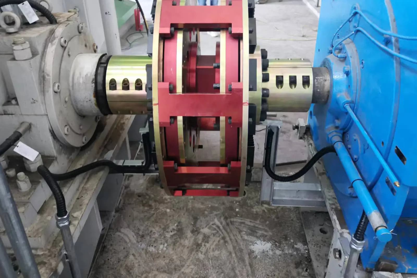
Representative industrial magnetic coupling installed between two rotating machinesRepresentative visual

Representative category visual; retention, materials, interfaces, and validation are confirmed for each assembly.

Photo by Benzhongo, resized and cropped from the original. Source · CC BY-SA 4.0

Capability-domain role

Magnetic Materials & Field Architecture →

Also interfaces with Precision Motion & Integrated Modules.

Magnetic assemblies connect field architecture to mechanical retention, interfaces, tolerance control, and subsystem integration. Exact architecture, manufacturing route, validation evidence, and supply commitment remain project-specific.

Available direction

What this review covers

  • Requirement review for retained, bonded, overmolded, potted, or mechanically integrated magnet assemblies
  • Magnetic circuit, mating interface, material, tolerance-stack, retention, and assembly-control planning
  • Prototype and validation planning for function, strength, runout, balance, environment, or cleanliness as applicable
Confirm for your project

What is not pre-confirmed

  • Universal claims for adhesive life, pull force, torque, balance, or ingress protection before design validation
  • Automatic responsibility for every mating part or customer-side assembly operation
  • Unverified in-house process, capacity, certification, or traceability claims
Available direction

Application routes

Use these routes to describe the function. Final architecture and component choices follow the operating conditions and interfaces.

Rotor, stator, and coupling assemblies

Where pole position, concentricity, retention, balance, and thermal exposure affect motion performance.

Holding, latching, and fixture modules

Where the steel return path, air gap, contact condition, mounting, and release behavior determine useful force.

Sensor targets and encoder rings

Where pole pattern, angular reference, runout, sensor gap, and assembly alignment must be controlled together.

Separated or filtered magnetic circuits

Where magnet placement, enclosure, cleanability, capture behavior, and service access are part of the requirement.

Confirm for your project

Engineering inputs that shape the decision

Items marked required are needed to close the basic requirement. Optional choices may remain open for the review.

Magnetic function

Required input

Define the required field, holding/release behavior, transmitted torque, pole pattern, or sensing result and its measurement condition.

Why it matters: The functional target determines the circuit and validation method.

Mating geometry

Required input

Provide the assembly envelope, interfaces, air gaps, shafts, housings, target steel, mounting datums, and customer-side constraints.

Why it matters: Mating geometry closes the magnetic circuit and controls fit.

Retention

Required input

State axial, radial, centrifugal, impact, vibration, shock, and service loads plus preferred bonding or mechanical constraints.

Why it matters: Retention must survive the combined mechanical and environmental load case.

Materials and compatibility

May remain open

Identify magnet, steel, polymer, adhesive, plating, potting, or restricted-substance requirements—or mark selections open.

Why it matters: Interfaces can fail through corrosion, thermal expansion, cure incompatibility, or galvanic effects.

Tolerance stack

Required input

Identify functional datums, position/orientation limits, runout, air-gap budget, and customer mating tolerances.

Why it matters: Individual part tolerances do not predict final functional alignment by themselves.

Loads and environment

Required input

Give speed, acceleration, torque, pressure, temperature, fluids, moisture, particles, sterilization, or cleaning exposure.

Why it matters: The real load/environment combination drives retention, protection, and validation.

Assembly constraints

Required input

Describe magnetized-state handling, adhesive cure limits, pressing, overmolding, potting, cleanliness, marking, and serviceability.

Why it matters: Assembly sequence can change magnetic orientation, damage protection, or lock in stress and contamination.

Available direction

Options to compare—not catalog promises

These are review directions. Availability, process route, evidence, and commercial terms remain project-specific.

Retention architecture

Adhesive bonding

Evaluate joint geometry, surface preparation, cure, gap, temperature, fluids, and process verification.

Mechanical capture

Evaluate sleeves, shoulders, fasteners, interference, or features against stress, corrosion, service, and balance.

Overmolding or potting

Evaluate material compatibility, pressure/temperature, shrinkage, void control, and inspection access.

Hybrid retention

Combine mechanisms only when load sharing and inspection responsibilities are explicit.

Functional architecture

Steel-backed holding circuit

Compare pole geometry, target steel, contact gap, release requirement, and mounting constraints.

Multipole ring or array

Compare pole pattern, angular reference, segment control, gap, and measurement method.

Rotor or coupling subassembly

Compare torque/speed, containment, runout, balance, corrosion, and failure containment.

Confirm for your project

Evaluation matrix

Compare candidate directions using application conditions and request evidence tied to a defined revision and test method.

Evaluation criteria and evidence to request for Custom Magnetic Assemblies
CriterionWhat to compareEvidence to request
Functional magnetic resultField, force, torque, or sensor response under the actual gap, mating material, alignment, and temperature.Defined fixture/mating part and a result tied to the assembly revision.
Retention marginWorst axial/radial/centrifugal/impact load after environmental conditioning and process variation.Joint design basis plus destructive or proof-test plan where appropriate.
Tolerance stackFinal air gap, position, runout, and alignment from component through assembly datums.Stack analysis and agreed dimensional/functional inspection record.
Assembly repeatabilityPolarity/orientation, adhesive or potting process, press conditions, cleanliness, and marking controls.Revision-specific work/inspection requirements to confirm for production.
Confirm for your project

Validation path

A useful result records the conditions, revision, method, output, deviations, and acceptance decision.

  1. Stage 1

    Interface review

    Close magnetic function, mating geometry, datums, loads, environment, and ownership boundaries.

    Review output: Interface-controlled requirement brief.

  2. Stage 2

    Prototype build

    Record assembly sequence and inspect orientation, critical dimensions, runout, joint condition, and functional output.

    Review output: Prototype build and inspection evidence appropriate to the project.

  3. Stage 3

    Application stress

    Exercise temperature, speed, vibration, shock, fluids, load, cycling, or cleaning exposures selected from the real use case.

    Review output: Agreed validation result and unresolved-risk list.

  4. Stage 4

    Production handoff

    Freeze BOM/drawing revisions, critical process checkpoints, acceptance criteria, markings, and packaging.

    Review output: Controlled release package subject to project confirmation.

Confirm for your project

Risk and control matrix

Project risks and controls for Custom Magnetic Assemblies
RiskConsequenceControl
Retention designed from nominal load onlyMagnets or subcomponents may shift or detach under speed, shock, heat, aging, or fluids.Define combined worst-case loads and validate the selected retention after conditioning.
Tolerance stack closes the air gapMagnetic result, clearance, noise, or wear can move outside the intended range.Use common functional datums and review assembly-level variation before drawing release.
Polarity or angular reference errorThe assembly may produce incorrect torque, sensor output, or attraction direction.Define a physical reference, polarity map, verification method, and marking convention.
Protection is damaged during assemblyCoating, adhesive, or encapsulation integrity can be lost before service.Review handling/contact points and inspect after the last risk-producing operation.
Confirm for your project

RFQ checklist

  1. 1Required magnetic function and measurement/acceptance condition
  2. 2Assembly and mating-part drawings with datums, gaps, interfaces, and ownership boundaries
  3. 3Load cases including speed, shock, vibration, torque, pull, pressure, or service forces
  4. 4Temperature, fluids, corrosion, cleanliness, sterilization, or outdoor exposure
  5. 5Retention preference and any prohibited adhesives, polymers, coatings, or processes
  6. 6Critical tolerance stack, runout, balance, pole/orientation, and marking needs
  7. 7Prototype validation, quality record, packaging, and traceability expectations
  8. 8Sample quantity, estimated demand, destination, timing, and revision status

Buyer FAQ

Why review the assembly instead of buying the magnet separately?

Useful field, force, torque, alignment, retention, and durability depend on the complete circuit and mechanical interfaces. Assembly-level ownership can reduce hidden tolerance and process gaps, but its exact scope must be agreed.

Can you work from our assembly drawing and BOM?

Yes, as a review starting point. Identify controlled characteristics, mating parts, expected loads/environment, approval records, and which materials or suppliers are fixed versus open.

How is retention validated?

The method should reflect the failure mode: proof or destructive force, torque, overspeed, thermal cycling, vibration, shock, fluids, or life cycling. The exact sequence and sample size are confirmed for the project.

Are Halbach arrays or multipole rings standard offerings?

They are architecture directions, not unconditional stock promises. Geometry, segment control, magnetization, assembly method, measurement, tooling, quantity, and supplier feasibility require review.

Continue the decision

Confirm for your project

Review the magnetic circuit and mechanical interfaces together

Share the function, assembly/mating geometry, datums, loads, environment, retention constraints, and acceptance method. Mark open material or process decisions honestly.

An initial review identifies missing inputs and next steps. It does not by itself confirm feasibility, performance, price, or delivery timing.