Remote handling · Inspection mechanisms · Service access
Radiation-zone motion planning
Plan the exposed mechanism and serviceable interfaces together. Magatom helps OEM teams define drive placement, feedback, cables and replaceable modules for radiation-zone remote-handling development.
Magatom Dynamics · Application engineering guide · Reviewed
Start with the mechanism and its assembly boundary
Start with the task to be performed remotely: inspection positioning, tool movement, component handling or another defined motion. Record the space, load path, available observation and recovery access. These constraints shape the assembly before a motor, transmission or feedback device is selected.
Map the mechanism, wiring and electronics to the exposure and maintenance zones supplied by the project team. A component near the working tool and a controller in an accessible location can have different conditions. Keep radiation-field information, temperature, working duration and replacement strategy attached to the actual parts and locations.
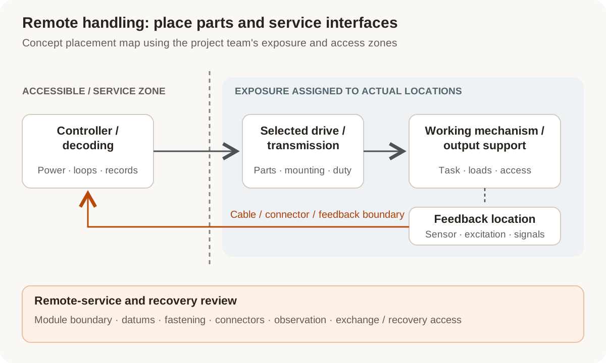
Concept placement map: assign exposure and maintenance conditions to each component location. The boundary represents project zones, not a shielding design or radiation rating.
Original Magatom application-engineering diagram. Scroll horizontally to inspect the diagram labels.
Compare drive placement with access and exposure
These layouts identify which components and interfaces need development. Compare them with the project team’s exposure map, installation space and remote task.
| Architecture | When to compare | Interfaces to review |
|---|---|---|
| Drive located with the mechanism | Compare when the working envelope calls for a compact local drive and output assembly. | Identify the motor, transmission, feedback, wiring and any local electronics exposed at that location. Define their component requirements and replacement access. |
| Separated drive and working output | Compare when the installation allows motion transmission from a location with different exposure or service access. | Review the intervening shaft, linkage or other selected transmission, its support, compliance, routing and measurement reference. Relocation creates interfaces that need their own evaluation. |
| Remotely replaceable motion module | Compare when planned module exchange is part of the maintenance strategy for the exposed equipment. | Define locating features, fastening, lifting/access, connectors and recovery provisions with the handling team. Identify what is replaced together and what remains installed. |
Connect exposure inputs to parts, signals and service decisions
A useful review associates every environmental and maintenance requirement with a component, location and operating sequence. It avoids reducing the complete mechanism to one material or sensor label.
Field, dose and working duration
Request the radiation type or field description, dose and dose-rate information, location, duration and duty from the responsible project team. Ionizing dose, displacement damage and single-event concerns describe different effects; keep the applicable quantities and assumptions with each component review.
Feedback sensor and decoding location
Compare sensing at the motor, transmission or working output. If a resolver is considered, define excitation, return signals, cable path and decoding electronics. Review the selected parts and locations; a feedback technology name does not establish their exposure performance.
Wiring, insulation and mechanical interfaces
Record exposed cables, connectors, winding insulation, seals, lubricants and other materials alongside temperature and motion conditions. Include bend routes, strain relief, mating access and the configuration records needed for the selected build.
Replacement, observation and recovery
Define how the system team observes position, reaches service interfaces and recovers or exchanges equipment. Map these tasks to module boundaries and datums. A locally compact assembly and a remotely serviceable assembly can lead to different connector and fastening choices.
Prepare the load, environment and interface brief
Send the values you know and identify the open choices. These are application inputs for review; keep the requested targets separate from the specifications of any selected component.
| Input | What to send | Decision it supports |
|---|---|---|
| Remote task and access | Tool/inspection function, travel, observation, installation space and remote access constraints. | Defines the working mechanism and handling boundary. |
| Motion and load cycle | Torque or force, speed, travel, support loads, dwell and holding states. | Connects the remote task to the drive and output support. |
| Exposure map | Project-supplied field type, relevant dose/rate quantities, locations and exposure duration. | Associates radiation requirements with actual component positions. |
| Other operating conditions | Temperature, atmosphere, contamination, cleaning and motion duty. | Records concurrent conditions rather than one isolated exposure label. |
| Component placement | Motor/transmission, sensing, electronics and accessible service-zone locations. | Makes relocation and interface trade-offs explicit. |
| Power and feedback paths | Excitation/signals, cable length/route, connectors, controller and decoding location. | Defines the electrical boundary around the selected feedback arrangement. |
| Maintenance and recovery | Module boundaries, exchange access, mounting datums, fastening and recovery requirements. | Integrates the maintenance strategy with the mechanical layout. |
| Evaluation and records | Selected parts/revision, project qualification scope, observations, quantity and development stage. | Links required evidence and next-build decisions to one configuration. |
Plan the prototype observations and next revision
01
Map the configuration and exposure
Agree the task, component locations, environmental inputs, cable paths and responsible evaluation scope with the project team.
Planned output: A location-linked component/interface brief and open-requirement list.
02
Define motion and component observations
Specify the representative load cycle, feedback reference, required exposure evidence and pre/post functional observations for the selected revision.
Planned output: An agreed evaluation plan identifying the conditions and records required.
03
Review remote service and the next build
Review installation, observation, exchange and recovery tasks with the handling team; record design changes and any evidence that must be renewed.
Planned output: An updated module/interface revision and next-stage acceptance inputs.
Shape the assembly-development scope
- A drive-placement and module-boundary comparison around the remote task.
- Defined motor, transmission, feedback, cable and remote-service interfaces.
- A prototype revision and project-specific evaluation/documentation brief.
Questions about radiation-zone remote handling
What radiation information belongs in the first motion brief?
Provide the project’s field description, component locations, relevant dose/rate information and duration, together with temperature and duty. Identify the responsible exposure/qualification requirements so component and interface choices can be reviewed against the actual installation.
Does selecting a resolver make the assembly radiation resistant?
A resolver is one possible feedback arrangement. Define the exact sensor, excitation, wiring and decoding electronics, then review the exposure requirements for each part and location. The complete configuration needs its own supporting evidence.
Should the motor or electronics be moved out of the working zone?
Compare the exposure and service benefit with the new mechanical, cable and feedback interfaces. Include support, compliance, routing, timing and available space. The useful choice follows the remote task and the actual zone layout.
Can a remotely replaceable module simplify the project?
It can create a useful maintenance boundary when exchange is part of the system plan. Define the datums, fasteners, connectors, handling access and recovery method with the team that will perform the remote tasks.
Can we bring already selected motors, cables or feedback parts?
Yes. Share exact part identities, interface drawings and applicable exposure documentation. The assembly review can focus on support, transmission, mounting, cable routing and service work around those fixed choices.
What should the first prototype review produce?
A configuration and location drawing, concrete open interfaces, an agreed motion/exposure evidence plan and remote-service decisions. Keep required records tied to the selected revision before planning the next build.
Connect the brief to component and project information
Technical reading behind the interface decisions
- NASA NEPP: Electronic radiation characterization and exposure conditions
Distinguishes ionizing dose, displacement damage and single-event effects in electronics; space examples do not qualify a remote-handling assembly.
- ITER Organization: Remote-handling equipment and maintenance tasks
A specific remote-maintenance system illustrates task, space, observability and replaceable-equipment requirements.
- Moog: Resolver excitation and signal-interface example, section 5.4
Explains the excitation, sine/cosine return signals and decoding interface of a particular resolver/drive arrangement; no radiation rating is implied.
Application & assembly review
Define the working mechanism and service boundary
Share the task, component/exposure map, load cycle, feedback and remote-access requirements. We can organize the motion interfaces and next prototype decisions around your project brief.
Bring a sketch, selected components or the open interface questions. Use the review to define the assembly scope and next development step.