Torque-speed and motion-system review

Custom Electric Motors and Motion Components

This path is for OEM teams selecting or adapting a motor, geared motor, frameless set, rotor/stator, or related motion component. Begin with the load at speed over time—not only a nominal wattage—then close voltage/current, duty, thermal path, envelope, feedback, transmission, controller, mechanical interfaces, and validation conditions.

Best starting point

Machine, robotics, instrument, pump, mobility, and automation teams matching a motion requirement to an electrical and mechanical architecture.

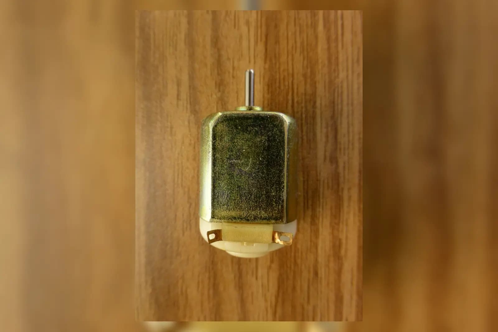
Representative compact brushed DC motor with shaft and terminal tabs visibleRepresentative visual

Representative category visual; architecture, interfaces, winding, feedback, and performance are confirmed for each project.

Photo by Nevit Dilmen, resized and composited over a blurred crop of the original. Source · CC BY-SA 3.0

Capability-domain role

Motors & Direct Drive →

Also interfaces with Electromagnetic Conversion & Actuation, Precision Motion & Integrated Modules.

Electric motors convert the magnetic and electromagnetic design into controlled rotary or linear motion and share the same integration interfaces. Exact architecture, manufacturing route, validation evidence, and supply commitment remain project-specific.

Available direction

What this review covers

  • Requirement review for brushed DC, BLDC, coreless, stepper, servo, torque, frameless, geared, hub/direct-drive, or linear motor directions
  • Review of motor, winding, magnetic circuit, feedback, brake, transmission, and mechanical/electrical interfaces
  • Prototype acceptance planning around torque-speed, current, temperature, noise, vibration, positioning, or application duty as applicable
Confirm for your project

What is not pre-confirmed

  • A guaranteed motor model, efficiency, life, acoustic level, or thermal limit before the duty and test conditions are agreed
  • A complete drive/control system unless controller, software, power supply, load, and ownership are explicitly in scope
  • Unverified catalog inventory, factory capability, certification, or production-volume promises
Available direction

Application routes

Use these routes to describe the function. Final architecture and component choices follow the operating conditions and interfaces.

Compact pumps, valves, and instruments

Where envelope, controllability, fluid load, noise, and continuous thermal conditions interact.

Robotics and automation axes

Where peak/continuous torque, acceleration, gearbox, feedback, brake, stiffness, and cable interfaces must be coordinated.

Fans, blowers, wheels, and direct drives

Where the load curve, operating points, commutation, efficiency, balance, and environmental exposure shape the motor.

Embedded motion subassemblies

Where the rotor, stator, magnets, windings, bearings, encoder, housing, or transmission require an OEM interface review.

Confirm for your project

Engineering inputs that shape the decision

Items marked required are needed to close the basic requirement. Optional choices may remain open for the review.

Torque and load

Required input

Provide continuous, peak, starting, holding, disturbance, and acceleration torque at the motor or output shaft.

Why it matters: Peak and continuous requirements load the electromagnetic and thermal design differently.

Speed and motion profile

Required input

Give operating speeds, direction changes, acceleration/deceleration, dwell, cycle time, and overspeed condition.

Why it matters: A single rated speed hides the real operating envelope and regenerative events.

Voltage and current

Required input

State bus/supply range, current limits, driver/controller, phase or commutation constraints, and power-quality conditions.

Why it matters: Winding and drive compatibility determine achievable torque-speed behavior and temperature.

Duty cycle and life

Required input

Provide time at each load/speed point, starts per hour, expected operating hours/cycles, and allowable maintenance.

Why it matters: Thermal equilibrium and wear cannot be reviewed from peak power alone.

Envelope and mass

Required input

Provide diameter/length/height limits, shaft centerline, mounting volume, moving mass, and service access.

Why it matters: Package limits influence motor topology, bearings, winding, feedback, and transmission choices.

Thermal environment

Required input

State ambient range, airflow, housing contact, coolant, neighboring heat, insulation constraints, and allowable surface/winding limits.

Why it matters: The mounting and cooling path determine usable continuous output.

Feedback and control

May remain open

Identify open/closed loop, Hall sensors, encoder/resolver, resolution, homing, commutation, control bandwidth, or mark open.

Why it matters: Feedback must match commutation, positioning, speed regulation, environment, and controller interfaces.

Transmission

May remain open

State direct drive or gearbox/belt/screw/coupling, ratio, efficiency, backlash, radial/axial load, and reflected inertia.

Why it matters: The transmission changes motor speed/torque, resolution, stiffness, efficiency, and life requirements.

Interfaces

Required input

Provide mounting, shaft/flange, bearings/load, connector/leads, cable, brake, controller, EMC, and environmental interfaces.

Why it matters: A feasible motor can still fail integration if its mechanical or electrical boundary is incomplete.

Available direction

Options to compare—not catalog promises

These are review directions. Availability, process route, evidence, and commercial terms remain project-specific.

Motor architecture

Brushed DC or coreless

Evaluate for control simplicity or low inertia while considering brush life, commutation, noise, and duty.

BLDC or servo

Evaluate for electronic commutation, controllability, efficiency, feedback, controller, and thermal integration.

Stepper

Evaluate torque-speed margin, resonance, heating at standstill, missed-step risk, and open/closed-loop needs.

Torque, frameless, axial-flux, or direct drive

Evaluate when package/integration benefits justify higher interface, air-gap, thermal, bearing, and control responsibility.

Motion integration

Gearmotor or transmission

Compare ratio, backlash, efficiency, noise, reflected inertia, output loads, life, and lubrication.

Feedback and brake

Select only after control mode, accuracy, safety behavior, power-off state, environment, and controller compatibility are clear.

Motor component set

Use rotor/stator or frameless supply only with explicit ownership of bearings, housing, air gap, assembly, balance, thermal path, and validation.

Confirm for your project

Evaluation matrix

Compare candidate directions using application conditions and request evidence tied to a defined revision and test method.

Evaluation criteria and evidence to request for Custom Electric Motors and Motion Components
CriterionWhat to compareEvidence to request
Torque-speed fitContinuous and peak points across supply tolerance, winding temperature, current limit, and transmission losses.Agreed duty points and a curve/test under defined electrical and thermal conditions.
Thermal marginWinding, magnet, bearing, electronics, and housing temperatures over the actual cycle and cooling path.Temperature test locations, ambient/mounting conditions, stabilization rule, and limits.
Motion qualitySpeed regulation, positioning, ripple/cogging, backlash, stiffness, noise, vibration, and transient response as relevant.Application-specific acceptance method rather than an undefined “high precision” claim.
Life and integration riskBearings, brushes, gears, insulation, connectors, cables, brake, lubricant, environment, and external loads.Life assumptions, derating basis, interface drawing, and validation plan to confirm.
Confirm for your project

Validation path

A useful result records the conditions, revision, method, output, deviations, and acceptance decision.

  1. Stage 1

    Duty review

    Map torque, speed, time, acceleration, supply, control, transmission, thermal path, and worst cases.

    Review output: Traceable operating-point and interface brief.

  2. Stage 2

    Bench sample

    Measure agreed electrical, torque-speed, temperature, feedback, noise/vibration, and dimensional characteristics.

    Review output: Revision- and condition-specific sample record.

  3. Stage 3

    Machine integration

    Run the real load cycle with controller, power supply, cooling, transmission, mounting, and protection behavior.

    Review output: Application acceptance evidence and updated risk list.

  4. Stage 4

    Release control

    Freeze winding/interface revision, test limits, documentation, software/controller dependencies, labels, and packaging.

    Review output: Controlled requirements for repeat supply, subject to agreement.

Confirm for your project

Risk and control matrix

Project risks and controls for Custom Electric Motors and Motion Components
RiskConsequenceControl
Sizing from nominal power onlyThe motor may overheat, stall, current-limit, or miss transient performance in the real duty.Review torque-speed-time points and the cooling path together.
Controller or supply mismatchAvailable voltage/current, commutation, feedback, braking, or EMC behavior may not support the selected motor.Include the actual controller, bus range, current limits, cable, feedback, and protection strategy in review.
External loads overlookedBearing, shaft, gearbox, noise, and life performance can degrade despite adequate electromagnetic sizing.Define radial/axial load, overhung distance, shock, alignment, coupling, and transmission loads.
Thermal test not representativeA free-air bench result can overstate continuous capability inside the machine.Validate using the intended mount, airflow/cooling, ambient, enclosure, and duty.
Confirm for your project

RFQ checklist

  1. 1Load table with continuous/peak/starting torque, speed, acceleration, dwell, and cycle time
  2. 2Supply/bus range, current limits, controller/driver, control mode, and braking behavior
  3. 3Envelope, shaft/flange/mounting drawing, external loads, mass, and service constraints
  4. 4Ambient, mounting/cooling path, enclosure, ingress, altitude, fluids, dust, and vibration
  5. 5Feedback, brake, connector/leads, cable, EMC, and software/interface requirements
  6. 6Transmission ratio, backlash, efficiency, stiffness, life, and output interface if used
  7. 7Acceptance tests for torque-speed, temperature, noise/vibration, positioning, or life
  8. 8Project stage, sample quantity, estimated demand, destination, timing, and documentation needs

Buyer FAQ

What should I send if I do not know the motor type?

Send the load and motion profile, power limits, package, thermal environment, controller context, mechanical/electrical interfaces, and acceptance criteria. Architecture can remain an engineering decision.

Is rated power enough for selection?

No. Rated power does not show starting/peak torque, the torque-speed curve, duty cycle, supply/current limit, transmission losses, thermal path, or transient behavior.

Can Magatom review a replacement motor?

Yes. Include the existing motor data, interface drawings, controller/supply, real load cycle, failure reason, acceptance tests, and which dimensions or behavior cannot change.

Are all motor architectures available for every project?

No. Listed architectures are comparison directions. Final feasibility, performance, documentation, tooling, quantity, supplier route, and timing require review and validation.

Continue the decision

Confirm for your project

Start with the load cycle, not a nominal wattage

Share torque-speed-time points, supply and controller limits, package, thermal path, feedback, transmission, interfaces, and acceptance needs. Unknown architecture choices can remain open.

An initial review identifies missing inputs and next steps. It does not by itself confirm feasibility, performance, price, or delivery timing.