Rehabilitation development · Exoskeleton research · Force-feedback rigs
Haptic actuator development
Connect interaction targets with the drive architecture. Magatom helps OEM teams compare passive resistance, output loads and feedback interfaces, then plan the next rehabilitation or haptic prototype.
Magatom Dynamics · Application engineering guide · Reviewed
Start with the mechanism and its assembly boundary
An assisted-motion mechanism and a force-feedback handle can both interact with a person, but they need different motion, contact and load descriptions. Identify the development stage, the system’s intended task and the mechanical interface first. A bench research rig, a wearable prototype and a completed device are distinct project scopes.
Write down how the mechanism should feel and behave in measurable terms: output torque over the motion cycle, resistance when moved externally, inertia, friction and feedback response. Evaluate these with the actual transmission, bearings and support structure. A motor torque number or a QDD label does not describe the complete interaction.
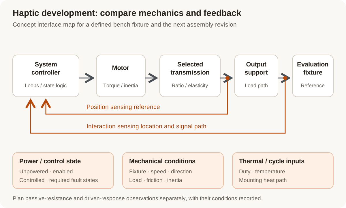
Concept interaction map: compare the mechanical output path with the feedback reference and controller boundary. A defined evaluation fixture supports the first prototype decisions.
Original Magatom application-engineering diagram. Scroll horizontally to inspect the diagram labels.
Compare the complete drive’s resistance and output behavior
Use the task and installation envelope to compare these actuation approaches. Include passive behavior, control interfaces and the intended measurement setup in the same decision.
| Architecture | When to compare | Interfaces to review |
|---|---|---|
| Direct-drive mechanism | Compare when the available motor package can produce the requested output cycle without a reduction stage. | Review torque and heat paths alongside rotor inertia, cogging/friction, output support, sensing and the mechanical contact interface. |
| Low-ratio or QDD arrangement | Compare when a reduction stage helps the output cycle while the project still prioritizes externally driven motion and limited resistance. | Review the actual motor, ratio, bearings, friction, reflected inertia, feedback and duty. Define how backdrive resistance will be measured in each state. |
| Series-elastic arrangement | Compare when an elastic transmission element is part of the required interaction or force-observation architecture. | Review stiffness, travel, sensing reference and control behavior together. Compare the dynamic response and package against the specific task rather than assuming one universal trade-off. |
Separate passive mechanics from closed-loop force behavior
The following review points turn a general request for a smooth or backdrivable joint into concrete component and prototype decisions.
Backdrivability at a defined state
Specify whether resistance is evaluated unpowered, with the drive enabled or under a control mode. Include direction, speed, output fixture and temperature. Bearing friction, transmission behavior and control action all affect what the complete mechanism presents at its output.
Mass, inertia and thermal duty
Locate mass relative to the moving interface and compare motor inertia through the selected transmission. Define the torque/speed cycle, dwell and heat path together. Peak output, continuing duty and externally driven resistance are separate comparison criteria.
Sensing location and controller timing
Map position feedback, any interaction-force/torque measurement and the controller loops. A motor-current estimate and an output measurement answer different questions. Define signal conditioning, timing and the mechanical path between the sensor and the contact reference.
Contact geometry and required state behavior
Review datums, travel, supports, fixture stiffness and the system team’s stopping, power-loss and recovery requirements. Include those states in the evaluation brief before moving from a constrained bench prototype to the next development stage.
Prepare the load, environment and interface brief
Send the values you know and identify the open choices. These are application inputs for review; keep the requested targets separate from the specifications of any selected component.
| Input | What to send | Decision it supports |
|---|---|---|
| Task and development stage | Research rig, wearable prototype or device development; intended interaction and current stage. | Establishes the assembly and evaluation scope. |
| Output motion and loads | Torque, speed, travel, dwell, external loads and motion cycle. | Separates the active output requirement from passive movement. |
| Passive resistance target | Backdrive/friction objectives with power/control state, direction, speed and temperature. | Defines a repeatable resistance comparison at the output. |
| Mass and installation | Envelope, mass placement, inertia, support arrangement and contact/fixture drawings. | Connects the drive package to the moving system and load path. |
| Thermal conditions | Duty cycle, supply/current constraints, mounting heat path and temperature objectives. | Defines the operating conditions for torque and resistance observations. |
| Feedback and control boundary | Position and interaction sensing, signal interfaces, controller loops and timing needs. | Assigns the measurement and controller work around the assembly. |
| Required system states | Startup, motion limits, stopping, loss-of-power and recovery behavior defined by the system team. | Makes state behavior part of the prototype review. |
| Evaluation and build plan | Fixture, measurement reference, planned observations, prototype quantity and next-stage criteria. | Ties the selected revision to a useful development decision. |
Plan the prototype observations and next revision
01
Define the constrained bench setup
Agree the output fixture, supported load, sensing references, control boundary and required states with the system development team.
Planned output: A common interface drawing and bench-evaluation brief for the selected revision.
02
Compare passive and driven behavior
Plan separate observations for backdrive resistance, torque response, motion and temperature, with each control/power state and condition recorded.
Planned output: Configuration-linked observations for the architecture and feedback decisions.
03
Review the next development stage
Compare the observations with the agreed targets, record changes and define the mechanical, control and system-level work needed before the next stage.
Planned output: An updated assembly revision, open-decision list and next-build acceptance inputs.
Shape the assembly-development scope
- A direct-drive, low-ratio/QDD or elastic-drive comparison around the interaction task.
- Defined motor, transmission, support, sensing and controller interfaces.
- A prototype revision and bench-evaluation plan before the next system-development stage.
Questions about rehabilitation and haptic motion
Does a low gear ratio guarantee a backdrivable actuator?
Compare the complete mechanism. Motor inertia, cogging, transmission and bearing friction, temperature and the drive/control state all matter. Define the output setup and operating conditions before comparing resistance measurements.
How should passive resistance and torque response be evaluated?
Use separate planned observations with a defined fixture and reference. Record the power/control state, direction, speed, load and temperature for resistance, and the command, sensing and timing conditions for driven response.
Is motor-current-based torque the same as an output torque measurement?
They describe different parts of the system. Identify the estimate or sensor, its location and the mechanical interfaces between it and the output. The project’s control and acceptance goals determine which measurement chain needs to be developed.
Should we choose series elasticity or a QDD architecture?
Compare the interaction task, passive resistance, output cycle, stiffness, sensing, control response and available package. The referenced research evaluates particular configurations; the useful project choice follows your mechanism and bench conditions.
Can catalogue actuators be used as development comparison points?
Yes. Compare their documented ratio, torque/speed, package and interfaces with your brief, then identify the mounting, feedback and evaluation work required. A research comparison does not assign a model to a clinical or human-use device.
What comes after a successful bench prototype?
Use the configuration-linked results to decide the next revision and development stage. Define the remaining system controls, intended-use evaluation and acceptance work with the responsible system team; component bench results alone do not complete that system decision.
Connect the brief to component and project information
Technical reading behind the interface decisions
- Original research, PubMed Central: Quasi-direct-drive actuator study
Study-specific characterization of backdrivability, torque and thermal behavior.
- Haption: Force-feedback technology and system interfaces
Haptic force feedback combines mechanics, sensing, electronics and real-time control rather than an actuator specification alone.
Application & assembly review
Define the interaction and the first assembly revision
Share the motion and passive-resistance targets, envelope, feedback/control interfaces and development stage. We can compare the drive architecture and organize the next prototype decisions.
Bring a sketch, selected components or the open interface questions. Use the review to define the assembly scope and next development step.