
What this review covers
- Requirement review for discrete permanent magnets and magnet sets
- Material, geometry, magnetization, coating, and tolerance direction
- Drawing, sample, packaging, and acceptance-plan preparation
Magnetic material and geometry review
This path is for OEM teams that need a permanent magnet defined around an operating requirement rather than a catalog grade alone. Begin with the magnetic objective, working gap, available envelope, temperature, environment, mating parts, and acceptance method; material and coating can remain open until those constraints are reviewed.
Best starting point
Design engineers and procurement teams defining a magnet by field, force, sensing, coupling, packaging, or replacement requirements.
 Representative visual
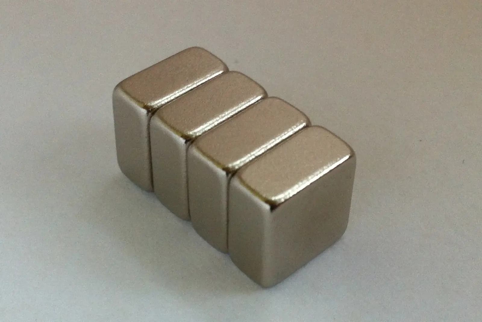
Representative category visual; geometry, material, coating, and magnetization are confirmed for each project.
Photo by Suradnik50, resized and cropped from the original. Source · CC BY-SA 3.0
Capability-domain role
Permanent magnets define the field source used across sensing, holding, electromagnetic conversion, motors, and integrated magnetic assemblies. Exact architecture, manufacturing route, validation evidence, and supply commitment remain project-specific.
Use these routes to describe the function. Final architecture and component choices follow the operating conditions and interfaces.
When pole pattern, air gap, sensor position, and field consistency drive the design.
When usable holding force depends on the complete magnetic circuit, contact condition, and safety factor.
When geometry, magnetization, retention, balance, temperature, and demagnetization margin interact.
When a limited envelope, close tolerances, cleanliness, and assembly handling matter.
Items marked required are needed to close the basic requirement. Optional choices may remain open for the review.
State the required field, force, torque contribution, sensor response, or reference part and the measurement location.
Why it matters: The objective defines what must be modeled or measured; a grade name alone does not.
Provide 2D/3D geometry, available envelope, pole faces, air gap, mating steel, and orientation constraints.
Why it matters: Circuit geometry and gap can dominate the useful field or force.
Share any required NdFeB, SmCo, ferrite, or AlNiCo direction—or mark material as not defined.
Why it matters: Material selection trades magnetic output, temperature behavior, corrosion risk, size, and cost.
Give continuous, peak, storage, and thermal-cycle conditions near the magnet.
Why it matters: Temperature affects reversible output and irreversible demagnetization risk.
Identify moisture, salt, chemicals, vacuum, cleanliness, radiation, or outdoor exposure.
Why it matters: The operating environment determines corrosion protection and material suitability.
State coating restrictions, appearance needs, adhesion interfaces, edge protection, or mark open for review.
Why it matters: Protection must be compatible with handling, bonding, temperature, and the real exposure.
Identify critical-to-function dimensions, datums, flatness, parallelism, and acceptable inspection methods.
Why it matters: Brittle magnetic materials need realistic tolerances tied to function and inspection.
Define direction, pole count or pattern, magnetized/unmagnetized delivery, and handling constraints.
Why it matters: Magnetization affects tooling, measurement, assembly safety, and packaging.
These are review directions. Availability, process route, evidence, and commercial terms remain project-specific.
Evaluate where compact magnetic output is important and temperature/corrosion controls can be defined.
Evaluate for elevated temperature or corrosion-sensitive programs where its trade-offs are acceptable.
Evaluate where corrosion resistance and cost matter more than maximum energy density.
Evaluate for specific temperature, stability, or geometry requirements with demagnetization behavior considered.
Choose only after geometry, output, tolerance, volume, and tooling assumptions are compared.
Match protection to the substrate, exposure, bonding process, thickness, and damage risk.
Consider when impact, corrosion, retention, or cleaning demands exceed a coating-only approach.
Compare candidate directions using application conditions and request evidence tied to a defined revision and test method.
| Criterion | What to compare | Evidence to request |
|---|---|---|
| Useful magnetic output | Field or force at the real working gap and temperature, not only remanence on a datasheet. | Agreed measurement fixture, position, orientation, tolerance, and sample report. |
| Demagnetization margin | Worst-case temperature, opposing field, circuit state, and assembly process. | Design review or simulation assumptions plus an agreed thermal/magnetic validation. |
| Environmental durability | Base material, coating system, edge condition, handling, and exposure sequence. | Coating specification and project-specific corrosion or environmental test plan. |
| Geometry and inspection | Functional datums and tolerances against feasible grinding, coating, and measurement methods. | Approved drawing, gauge/inspection method, and dimensional sample record. |
A useful result records the conditions, revision, method, output, deviations, and acceptance decision.
Confirm the magnetic objective, circuit geometry, environmental limits, and measurement definition.
Review output: Reviewed requirement brief with open assumptions.
Measure critical dimensions and the agreed magnetic characteristic on representative samples.
Review output: Dimensional and magnetic sample results tied to revision.
Test in the intended air gap, mating circuit, temperature range, and assembly condition.
Review output: Buyer-approved application acceptance record.
Freeze drawing, material/protection requirement, magnetization, inspection, labeling, and packaging expectations.
Review output: Revision-controlled order and quality requirements.
| Risk | Consequence | Control |
|---|---|---|
| Choosing by grade name only | The part can miss application field or force because gap and circuit geometry were ignored. | Define the measurement point and validate the complete magnetic circuit. |
| Edge or coating damage | Corrosion or contamination can develop after handling or assembly. | Review edge geometry, handling, packaging, coating thickness, and incoming inspection. |
| Thermal demagnetization | Magnetic output may not recover after the worst operating event. | Review the load line and validate at maximum temperature and opposing field. |
| Unsafe magnetized handling | Parts can chip, attract debris, pinch operators, or damage adjacent components. | Agree magnetization state, spacers, shielding, labeling, and packing method before shipment. |
Yes. Provide the operating requirement, space, gap, temperature, environment, mating circuit, and acceptance method. Grade and protection can remain engineering decisions until those constraints are compared.
A reference sample can help start the review, but a controllable order still needs agreed dimensions, magnetic acceptance criteria, material/protection direction, magnetization, and revision ownership.
State the mating material, contact area and finish, air gap or coating, pull direction, temperature, test method, and required safety factor. A nominal pull-force number without those conditions is not comparable.
No. They are evaluation directions. Final feasibility, supplier route, documentation, tooling, quantity, and timing are confirmed for the reviewed project.
Share the application, working gap, geometry, temperature, environment, magnetization, and acceptance method. Unknown material or coating choices can remain open for review.
An initial review identifies missing inputs and next steps. It does not by itself confirm feasibility, performance, price, or delivery timing.