Mechanical assembly
Servo motor, planetary gearbox, mating adapter and motor-side holding brake. Review the mounting face, shaft connection, orientation and load support together.
Motor · Planetary gearbox · External drive kit
Bring the motor, gearbox, holding brake and drive interfaces into one defined supply package. Configure a geared servo assembly with matched external drive components, wiring and integration documents around your rotary-positioning application.
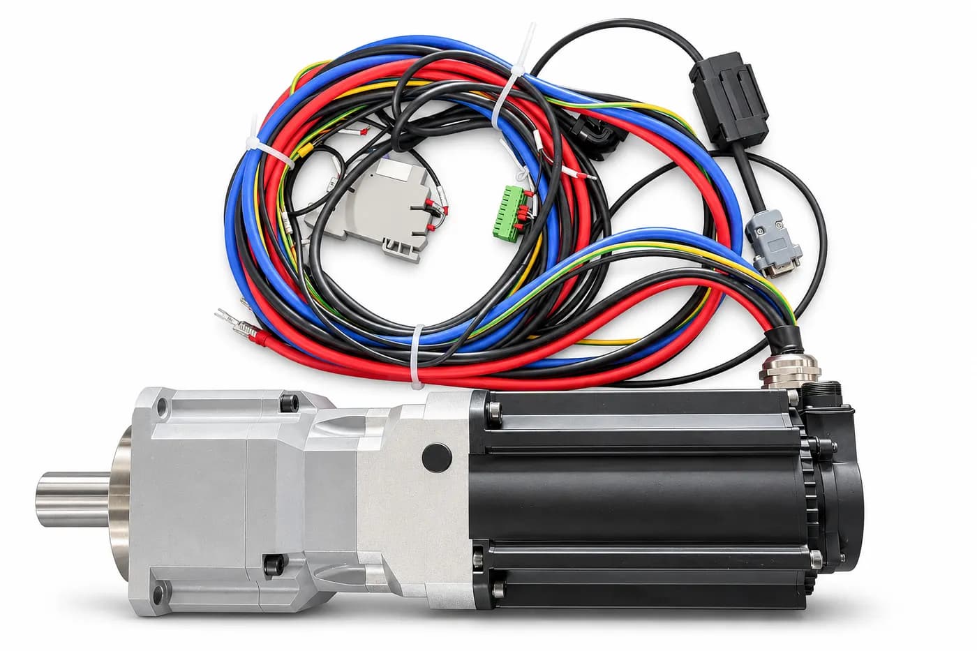
Geared servo assembly with matched power, feedback and brake wiring.
Product view prepared from the project photograph.
Build your drive package
Servo motor, planetary gearbox, mating adapter and motor-side holding brake. Review the mounting face, shaft connection, orientation and load support together.
Separate CANopen servo drive, electrical braking unit and resistor, brake relay, power/feedback/brake cables and controller connections.
Component list, configuration datasheet, external-envelope CAD and the agreed wiring/communication references. Define commissioning and acceptance work in the project scope.
Plan the cabinet, DC power supply, load support and controller alongside the actuator. Select shaft output against the operating cycle and installed thermal path.
Reference configurations
The reference builds pair a nominal 48V, 4kW PMSM motor component with a motor-side holding brake and 17-bit single-turn absolute motor-position feedback. The 4kW figure is a motor nameplate reference; the selected assembly duty and cooling determine its useful shaft output.
Higher reduction for loaded positioning and holding-duty review.
Lower reduction for higher output-speed positioning review.
Use the selected configuration drawing for mounting, fits, connector clearance and the quoted revision. The series photograph illustrates the assembly and harness arrangement.
Download the configuration overview PDF →Review mating flange, pilot and shaft connection, bearing/load support, mounting orientation and the space around the motor connectors.
Define cable lengths, connector types, power/feedback/brake routes, cabinet I/O and the controller interface.
Specify stationary holding separately from the motion profile, regenerative-energy path and resistor duty.
Agree engineering/NRE, sample hardware, wiring, documents and acceptance outputs, then use the accepted revision for repeat orders.
Shaft torque and speed, acceleration, reversals, dwell and cycle frequency.
Payload inertia, centre of gravity, overhung loads and the supporting bearing arrangement.
Nominal voltage, available current, cable run and regenerative-energy handling.
Mounting drawing, shaft connection, adapter space and cable/connector clearance.
Stationary holding, brake release and the required deceleration cycle.
Your controller, CANopen requirements and any additional sensing channel.
Quantity, mounting orientation, drawings, configuration records and acceptance scope.
Project experience
A rotary-positioning order used three actuator sets in two gearbox configurations, with matched cable harnesses, external drive/braking components and configuration documents.
Read the assembly and packing case →The mechanical assembly combines the servo motor, planetary gearbox, adapter and motor-side holding brake. A selected package can also include the separate servo drive, electrical braking unit and resistor, relay, cable harnesses and configuration documents. The quotation identifies the items and work included.
Start with shaft torque and speed, acceleration, payload inertia and duty. The 30:1 reference provides more reduction; the 8:1 reference suits review of higher-speed positioning. Review the motor, drive, supply and installed thermal path together before fixing an output rating.
The reference builds use a separate cabinet-mounted CANopen servo drive. The power supply, drive, electrical braking components and controller connections need space and wiring in the machine layout.
The motor-side holding brake parks a stationary axis and uses 24V DC to release. The separate braking unit and resistor deal with energy returned to the DC bus during deceleration. Define stopping duty and holding requirements separately in the application brief.
Share the mating drawing and the interfaces that need to change. The review can cover adapter and mounting details, output connection, cable length, connectors, mounting orientation and control connections. Agree the configuration revision and acceptance work before the prototype is built.
The documented reference package has a motor-position encoder. If your application needs an independent force or torque measurement, include the load path, measurement range and signal requirements so a separate sensing configuration can be evaluated.
Yes. Select a reference configuration or describe the envelope you need. Request the external-envelope STEP, mounting references and the documentation for the package under review. The overview PDF helps prepare the brief; the quotation and configuration drawing define the selected assembly.
Send the load cycle, mounting envelope, available DC supply and current, controller interface, required documents, quantity and project timing. The quotation separates hardware, interface work, wiring, commissioning support and agreed acceptance records.
Your next rotary axis
Send output torque and speed, duty and inertia, the mounting envelope, DC supply and current capability, controller interface and quantity. Mark open questions so the first review can focus on the decisions that shape the package.