Pipes · Storage tanks · Steel wind towers · NDT interfaces
Magnetic crawler drive integration for steel-surface inspection
Develop the magnetic contact and drive around the real inspection path. Magatom helps OEM teams connect magnetic assemblies, geared motion, payload and probe interfaces in a reviewable crawler subassembly brief.
Magatom Dynamics · Application engineering guide · Reviewed
Start with the mechanism and its assembly boundary
A steel-surface inspection crawler must maintain useful contact while carrying its own mass, probe, cables and other equipment through the planned route. Start with the material, coating, curvature and transitions, then map the drive and inspection tasks to that surface. A tank wall, a curved pipe and a steel tower do not describe the same contact geometry.
Treat adhesion, traction and overturning loads as separate questions. A magnet pull-force figure describes a particular separation test; the crawler brief must also address motion along the surface, the position of the payload and tether loads. That distinction connects magnetic component selection with chassis geometry, wheel or track contact and the motor/transmission interfaces.
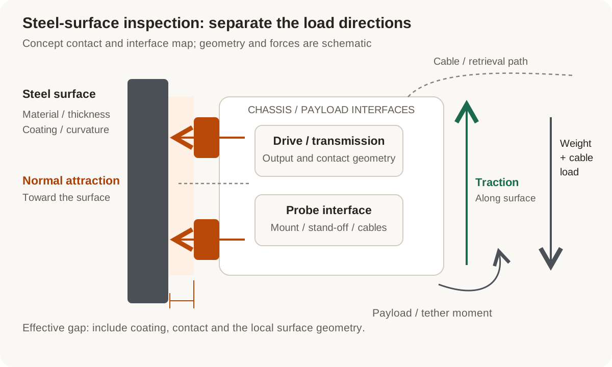
Concept contact and load-path map: normal magnetic attraction, tangential traction and payload moments need separate review. Surface geometry and cable routing complete the mechanical brief.
Original Magatom application-engineering diagram. Scroll horizontally to inspect the diagram labels.
Compare the contact architecture before sizing the drive
Choose a starting point around the scan path and the required probe motion. Keep contact geometry, steering and the installation envelope visible in the architecture comparison.
| Architecture | When to compare | Interfaces to review |
|---|---|---|
| Magnetic wheel arrangement | Compare when discrete contact locations and wheel packaging suit the surface curvature and scan route. | Review wheel geometry, effective magnetic gap, steering/drive interfaces, payload position and transitions between contact locations. |
| Magnetic track arrangement | Compare when the route calls for a distributed contact layout and a track-based chassis can fit the equipment. | Review belt/contact materials, supported contact length, turning resistance, curvature and how the contact changes over an obstacle. |
| Separate adhesion and propulsion functions | Compare when magnetic retention and the driven contact need different geometry or adjustment. | Define the connection between the magnetic module, running surface, chassis and transmission. Review release, adjustment and probe access as part of the same layout. |
Separate attraction, traction and load moments
These are review questions for the complete mechanism. Record the configuration and surface condition whenever forces or performance are compared.
Normal attraction at the working gap
A pull-force test acts away from the steel. Coating, curvature and incomplete contact change the working separation and magnetic circuit. Define the actual target material and geometry before comparing magnet dimensions or force data.
Tangential traction along the surface
The available traction also depends on contact and friction. Review the running material, contamination and required driving force, including cable drag. Keep sliding or driving behavior separate from a normal pull-off figure.
Payload and tether moments
Record where the centre of gravity, probe forces and cable attachments act relative to the contact layout. Review how these loads can redistribute contact or create a tendency to peel away from the surface.
Transitions and inspection interfaces
Map welds, gaps, changes of curvature and non-ferromagnetic sections along the route. Include the probe stand-off, cable sweep and retrieval arrangement when defining which transitions the prototype must evaluate.
Prepare the load, environment and interface brief
Send the values you know and identify the open choices. These are application inputs for review; keep the requested targets separate from the specifications of any selected component.
| Input | What to send | Decision it supports |
|---|---|---|
| Contact material | Actual surface alloy/material, thickness and confirmation of the magnetic contact path. | Establishes whether a ferromagnetic adhesion concept is relevant to the route. |
| Geometry and effective gap | Pipe/tank diameter, internal or external travel, coatings and expected gaps. | Connects magnetic and running-contact geometry to the real surface. |
| Surface condition | Rust/scale, moisture, lubricant, debris and preparation constraints. | Identifies magnetic-gap and traction conditions that need evaluation. |
| Payload and moments | Crawler equipment mass, centre of gravity, probe forces and attachment positions. | Makes contact-load distribution and overturning effects part of the layout. |
| Cable and retrieval arrangement | Cable route, drag/weight, attachment points, retention and recovery requirements. | Captures loads and access requirements that a drive-only comparison would miss. |
| Motion and transitions | Scan speed, starts/stops, turning, duty and weld/gap/obstacle profiles. | Defines representative driving and contact-change events for the prototype. |
| Probe and drive interfaces | Probe mount/stand-off, chassis datums, wheel/track space, motor and feedback constraints. | Connects the inspection function to the magnetic and drive assemblies. |
| Acceptance and project stage | Intended evaluation surface, load cases, observations, quantity and build stage. | Turns the assembly brief into a configuration-linked development plan. |
Plan the prototype observations and next revision
01
Define the surface and load cases
Agree representative surface samples, contact geometry, coating/gap conditions, payload positions and cable loads.
Planned output: A contact/load brief and a list of scan-path transitions to evaluate.
02
Evaluate contact and driven behavior
Plan separate attraction, traction, turning and transition observations for the selected assembly and agreed operating arrangements.
Planned output: Configuration-linked observations showing which contact or interface decisions need revision.
03
Integrate the inspection equipment
Review probe access, mounting, stand-off, cable sweep and the system team’s retention/retrieval requirements through the planned route.
Planned output: An updated assembly/interface revision and acceptance inputs for the next build.
Shape the assembly-development scope
- A magnetic contact and drive architecture brief linked to the actual surface and scan path.
- A shared interface definition for magnetic modules, running contact, chassis, probe and cables.
- An agreed prototype evaluation scope and revision plan for the selected assembly.
Questions about magnetic crawler drive integration
Will a magnet pull-force rating predict the vertical crawler payload?
Use pull-force data with its test conditions as one input. The complete crawler review also needs tangential traction, payload moments, effective gaps, cable loads and the actual surface condition. Evaluate these together for the selected contact and chassis arrangement.
Can one magnetic contact design cover a wind tower and a composite blade?
Define the material along the inspection path. A magnetic adhesion arrangement needs a suitable ferromagnetic path, such as the specified steel surface. A composite blade without that path needs a different contact or access strategy and a separate mechanism brief.
What changes when the crawler crosses a weld or surface transition?
The contact layout, effective gaps, load distribution and required driving behavior can change. Send the transition geometry and intended direction of travel, then agree which conditions the prototype should evaluate with its payload and cables.
Should we include the tether in the first drive discussion?
Yes. Include its route, mass or drag, attachment position and the system team’s retention/retrieval requirements. These influence loads, moments, access and the practical scan path before the motor and transmission are selected.
Can we bring an existing probe, chassis or motor?
Yes. Share the selected parts, mounting datums, available envelope and open interfaces. The review can concentrate on the magnetic contact, transmission, probe mounting or other assembly work still needed around those fixed choices.
What should the first prototype evaluation record?
Agree the surface, gap/coating, payload, cable arrangement and motion events first. Link observations to the tested configuration so the next revision addresses specific contact, traction, turning or probe-interface decisions.
Connect the brief to component and project information
Technical reading behind the interface decisions
- Eddyfi Technologies: Magnetic inspection crawler architecture
Ferrous-surface contact and defined crawler configuration requirements.
- K&J Magnetics: How Much Will a Magnet Hold?
Pull-force test geometry, surface gaps and friction in vertical holding.
- Eddyfi Technologies: Swift, Scorpion2 and R-Scan User Manual, version 2.2
Printed pages 45–46 (PDF pages 63–64): surface preparation, obstacles, ferrous contact and tether requirements for the documented crawler.
Application & assembly review
Build the contact and drive brief around your scan path
Send the surface material, curvature, coating or gap, payload, cable loads and inspection interfaces. Identify the components you have already selected and the assembly decisions that remain open.
Bring a sketch, selected components or the open interface questions. Use the review to define the assembly scope and next development step.