Downhole tools · Narrow envelopes · Thermal and mechanical interfaces
Downhole drive integration
Fit the drive around the tool’s working envelope. Magatom helps OEM teams connect torque duty, thermal paths, transmission, pressure boundaries and feedback in a downhole assembly brief.
Magatom Dynamics · Application engineering guide · Reviewed
Start with the mechanism and its assembly boundary
Begin with the tool function: valve movement, positioning, an instrument mechanism or another defined output. Record diameter and length constraints with mounting, shaft and cable interfaces. The available tube diameter can make the axial arrangement as important as the nominal motor power.
Describe the operating cycle and the environment at the actual drive location. External fluid temperature, housing temperature and winding temperature are different inputs or observations. Review them alongside pressure boundaries, fluid exposure, shock/vibration and service requirements before selecting a motor or transmission.
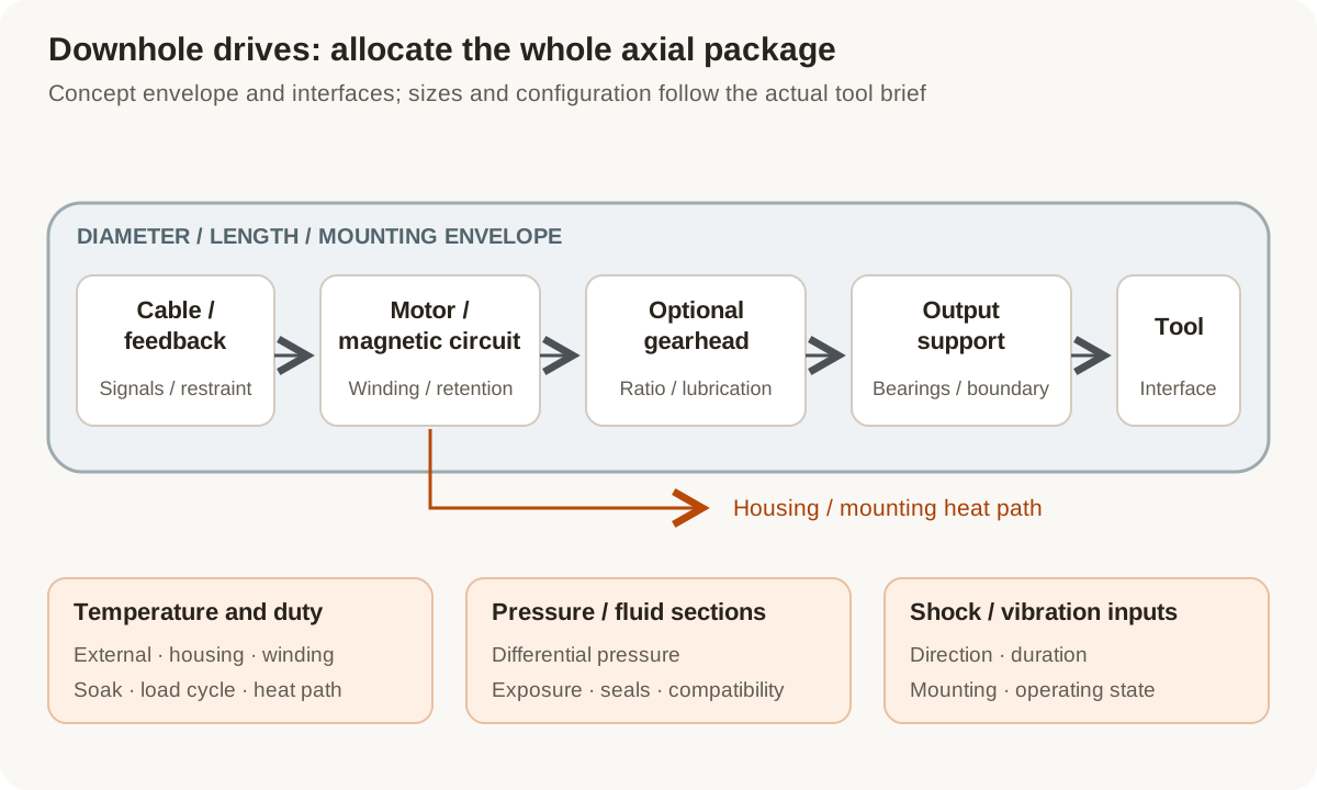
Concept axial layout: review envelope, drive chain and tool interfaces together. Thermal, pressure and vibration inputs apply to the selected configuration rather than one magnet or motor label.
Original Magatom application-engineering diagram. Scroll horizontally to inspect the diagram labels.
Compare the axial drive chain within the tool envelope
Use the output cycle and installation boundary to compare these starting layouts. Identify the complete support, coupling and electrical package rather than allocating space to the motor alone.
| Architecture | When to compare | Interfaces to review |
|---|---|---|
| Motor with an axial gearhead | Compare when the required output torque/speed benefits from reduction and the axial package can fit the tool. | Review ratio and duty alongside shaft support, gear/bearing lubrication, fluid arrangement, mounting and the complete stack length. |
| Direct-drive output | Compare when the motor can be packaged and sized for the required output without a reduction stage. | Review the available diameter, torque/speed cycle, rotor/output support, thermal path and feedback placement together. |
| Separated drive and tool mechanism | Compare when the tool layout permits the drive and working output to occupy different sections. | Define the intervening shaft/coupling, supports, pressure passages and service connections. Include their compliance, alignment and thermal interfaces in the comparison. |
Review heat, materials and mechanical exposure as one configuration
A temperature target or narrow motor outline is only part of the assembly definition. The following decisions connect the tool envelope with its continuing duty and environment.
Ambient temperature and internal heat
State external fluid/housing conditions and the powered load cycle separately. Identify the intended heat path, dwell and startup/soak sequence. A winding-temperature observation and an ambient-temperature requirement describe different parts of the thermal review.
Magnetic, winding and retention choices
Review candidate magnet grades with their magnetic circuit and operating temperature, alongside winding insulation, rotor retention, adhesives or other joining methods. SmCo may be a material to compare; its material data does not establish the temperature capability of the complete drive.
Transmission, bearings and fluid boundary
Connect torque, speed and side loads to the gearhead and support bearings. Specify the actual pressure differential, fluid contact, lubrication and seal/coupling arrangement. Review these interfaces together with thermal exposure and installation clearances.
Shock, feedback and cable connections
Provide the project’s shock/vibration description, mounting directions and operating states. Review the selected feedback device, electronics location, connectors and cable restraint with the mechanical package and required service access.
Prepare the load, environment and interface brief
Send the values you know and identify the open choices. These are application inputs for review; keep the requested targets separate from the specifications of any selected component.
| Input | What to send | Decision it supports |
|---|---|---|
| Tool function and output | Required action, torque/force, speed, travel, holding and mating output geometry. | Defines what the drive must do at the tool interface. |
| Axial installation envelope | Diameter, length, mounting datums, shaft/support space and cable exit. | Allocates the complete motor/transmission/interface stack. |
| Operating cycle | Moves, dwell, startup, repetition and continuing/short-duration load states. | Connects output selection to thermal and transmission duty. |
| Thermal conditions | External fluid and housing temperatures, soak, heat paths and required observations. | Separates the environment from powered internal heating. |
| Pressure and fluid exposure | Pressure differential, fluid composition, filled/dry sections and sealing interfaces. | Defines the boundary and compatibility review for each section. |
| Shock and vibration | Project-defined spectrum/pulses, mounting direction, duration and operating state. | Sets the mechanical exposure cases for the selected configuration. |
| Feedback and electrical path | Power, sensing location, controller/electronics location, signals, connectors and restraint. | Makes the complete electrical package part of the tool layout. |
| Evaluation and build plan | Exact selected parts, material records, evaluation conditions, quantity and project stage. | Ties qualification questions and acceptance records to one revision. |
Plan the prototype observations and next revision
01
Close the axial and boundary layout
Agree tool datums, stack length, shaft supports, fluid/pressure sections and the power/feedback path.
Planned output: An assembly envelope and interface drawing with open component choices identified.
02
Define the combined operating cases
Agree soak, powered duty, pressure/fluid and mechanical-exposure cases, their sequence and the observations required for the selected revision.
Planned output: A configuration-linked evaluation plan with separate thermal, mechanical and functional questions.
03
Review the next tool build
Compare the agreed records, identify service/installation issues and decide what must be re-evaluated after motor, material, bearing or boundary changes.
Planned output: An updated tool-drive revision and next-build acceptance inputs.
Shape the assembly-development scope
- An axial motor/transmission comparison within the real tool envelope.
- Defined output, support, thermal, fluid and feedback interfaces.
- A prototype revision and agreed operating/evaluation record requirements.
Questions about downhole tool drives
Does a high-temperature magnet establish the motor’s temperature rating?
No. Review magnet grade and magnetic operating point with the winding, insulation, bearings, retention, lubrication, feedback and the actual heat path. Temperature requirements and evidence belong to the selected assembly configuration.
Is external well temperature the same as winding temperature?
They are different quantities. State the external and housing conditions, soak and powered load cycle, then define the internal temperatures or other observations needed for the project. The thermal review connects them through the selected structure and heat path.
Should a narrow tool use a direct motor or a gearmotor?
Compare the required output cycle with the available diameter and stack length. Include supports, coupling, lubrication/fluid arrangement, feedback and duty before choosing the reduction and motor package.
Can we assume the whole drive sees the same pressure?
Draw the actual filled, dry and exposed sections and identify differential pressure at each passage. This establishes which housings, seals, connectors and other interfaces need review for the intended operating sequence.
What shock or vibration information is useful?
Supply the project’s spectrum or pulse description, direction, duration, mounting arrangement and operating state. Link these inputs to the selected parts and evaluation plan rather than relying on an undefined ruggedness label.
Can an existing downhole tool keep its selected interfaces?
Yes. Share fixed output, support, cable, controller and housing interfaces with their available documentation. The review can focus on the motor, transmission, magnetic components or assembly work needed within that boundary.
Connect the brief to component and project information
Technical reading behind the interface decisions
- maxon: Downhole drive design considerations
Dedicated downhole motor-design conditions and complete-assembly considerations.
- Arnold Magnetic Technologies: Temperature Effects on Magnetic Output, TN 0303
Magnetic behavior depends on temperature, grade and magnetic operating point; material data is not a complete motor temperature rating.
Application & assembly review
Build the drive brief around the actual tool envelope
Send the tool function, diameter/length, output cycle, thermal and pressure sections, mechanical exposure and electrical interfaces. We can compare the assembly layout and next prototype decisions.
Bring a sketch, selected components or the open interface questions. Use the review to define the assembly scope and next development step.