Custom motor development · Stator & rotor prototypes

Custom Permanent-Magnet Motors, Built Around Your Application

Start with a torque-speed target, an installation envelope or an existing motor specification. Work with Magatom to define the motor design, stator-rotor prototype and validation plan, then prepare the accepted revision for pilot production.

Reviewed

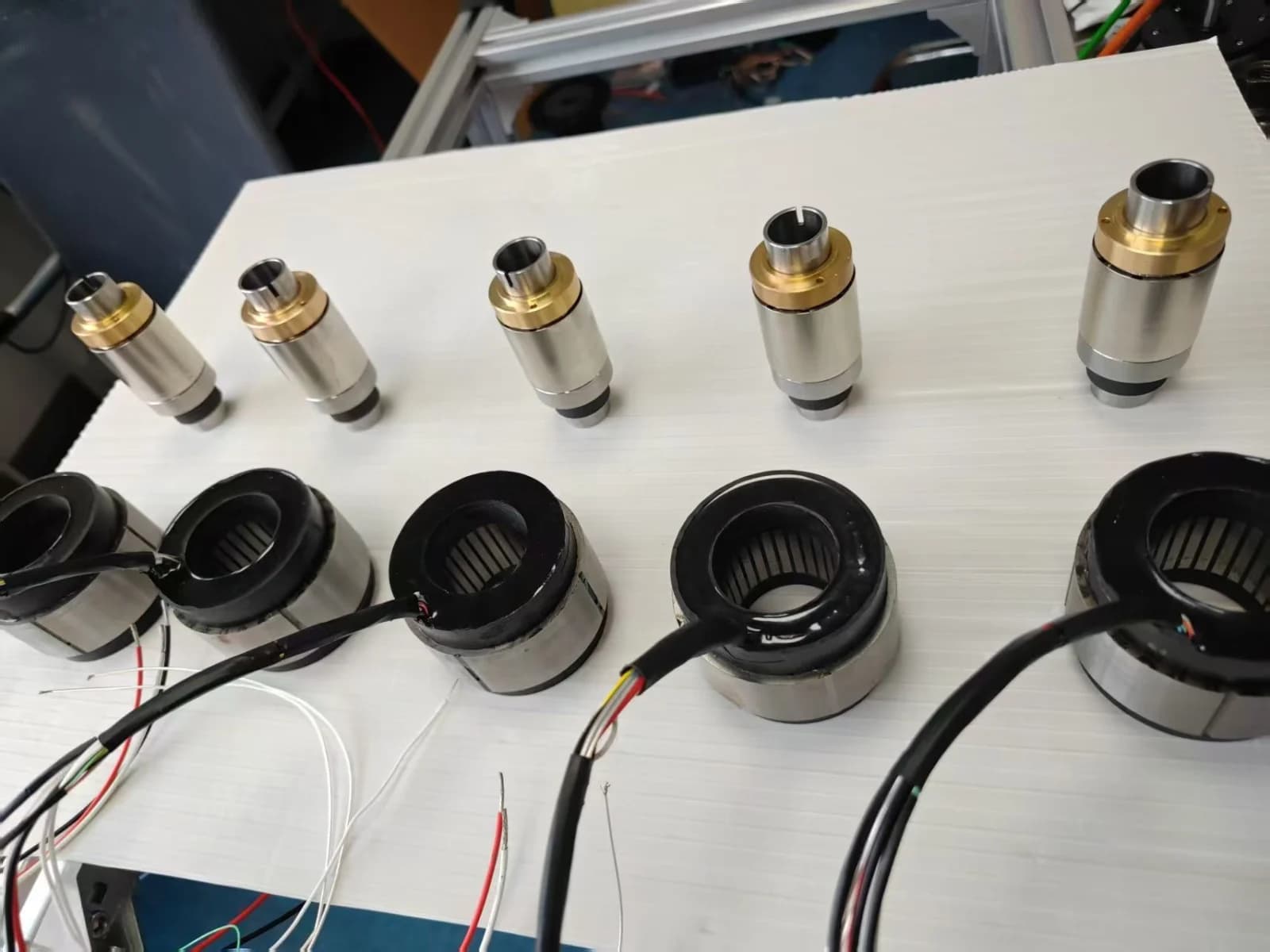
Cylindrical motor component samples arranged in two rows on a white work table

Motor component samples.

Photo provided by the Magatom site owner.

Three ways to start

Bring your requirement, active-part envelope or existing motor

Custom motor from requirements

A standard motor may fit the space but miss the operating cycle. Bring the load duty and fixed interfaces so the design review starts from your machine, including the space for feedback and cooling.

Discuss a Custom Motor →

Stator and rotor prototype sets

Develop active motor parts for an embedded assembly. Define the stator and rotor envelope together with support, retention, air gap, heat transfer and electrical connections.

Discuss a Stator-Rotor Set →

Existing motor alternative

Use your current motor specification as a comparison baseline. Identify what must stay compatible, what can change and which application tests will decide whether a candidate is acceptable.

Review a Motor Alternative →

Motor development brief

Define the duty and interfaces before selecting the winding

Send what you know. A sketch, operating cycle and open questions are enough to begin a review; topology, winding and feedback choices can remain development decisions.

Torque, speed and time

Why it matters
Acceleration, reversal, dwell and repeated loads shape the winding, current and heating questions.
What you can send now
A duty-cycle sketch, load curve or operating points; mark continuous and intermittent demands.

Supply and drive

Why it matters
The available voltage, current limits and drive behavior constrain the useful torque-speed range.
What you can send now
Supply limits and drive model, or the control hardware still to be selected.

Motor envelope

Why it matters
Diameter, active length and bore compete with winding space, rotor support and cooling.
What you can send now
A sketch or CAD envelope with fixed and flexible dimensions identified.

Mounting and load support

Why it matters
Shaft, bearings, datums and load paths determine how the active parts fit the machine.
What you can send now
Mating drawing, mounting concept, radial/axial loads or open support questions.

Cooling and ambient

Why it matters
The installed heat path and operating conditions determine how thermal predictions should be checked.
What you can send now
Ambient conditions, duty and proposed housing/cooling contact; unknowns are acceptable.

Feedback and connections

Why it matters
Rotor-position feedback, commutation, leads and connectors must match the drive and assembly.
What you can send now
Encoder/resolver or Hall requirements, drive interfaces and available cable space.

Exposure and acceptance

Why it matters
Contamination, vibration, temperature and service expectations define the prototype evaluation.
What you can send now
Environment description, test priorities and any required acceptance method.

Project stage and quantities

Why it matters
Design, tooling, samples and testing need a defined scope before pilot and production planning.
What you can send now
Current stage, prototype/pilot needs, future production plans and target dates where known.

Stator and rotor integration

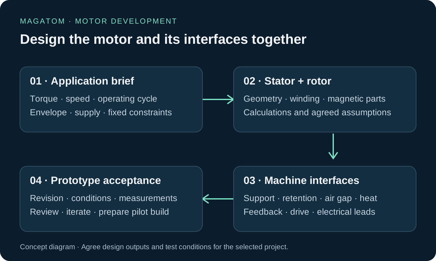
A stator-rotor set becomes part of your machine structure

A housed motor brings its support structure with it. A matched active-part set provides the wound stator and permanent-magnet rotor for integration into your machine. Define the housing, load support, sensing and drive alongside those parts to establish the complete axis scope.

Concept map linking motor requirements, stator and rotor parts, machine interfaces, and prototype acceptance

Motor development interface map: active parts, machine support, heat path, feedback and acceptance.

Original Magatom concept diagram.

Open the interface map at full size

Housing, shaft and bearings

Define the structure that supports the stator and rotor, the load path, locating datums and assembly access.

Retention and air gap

Agree the retention method, fits, concentricity and clearance checks across assembly, temperature and operating loads.

Thermal path

Define heat transfer into the machine, winding-temperature observation and the conditions used for analysis and testing.

Feedback and drive

Agree sensing location, commutation reference, winding/drive compatibility, cable routing and the work included in the assembly scope.

Discuss a Stator-Rotor Set →

Motor alternative development

Compare an alternative against the motor’s installed job

Send the current motor model, datasheet or available drawing, the operating cycle, control hardware and reason for considering a change. Mark each interface fixed, changeable or still open. Matching rated power or a flange is only part of establishing interchangeability.

Envelope and mounting

Fixed, changeable or open?
Which diameter, length, shaft, flange and connector locations are fixed? Which can change?
How to establish acceptance
Interface drawing and dimensional checks for the proposed revision.

Load support and dynamics

Fixed, changeable or open?
How are radial/axial loads supported? What inertia, acceleration and reversal must the axis handle?
How to establish acceptance
Support/retention review and evaluation with the representative load cycle.

Supply, winding and drive

Fixed, changeable or open?
Compare voltage/current limits, electrical parameters, commutation and controller requirements.
How to establish acceptance
Electrical checks and operation with the agreed drive and supply.

Feedback and wiring

Fixed, changeable or open?
Compare sensor interfaces, reference alignment, pin assignments, leads and cable routing.
How to establish acceptance
Documented interface and functional checks of the chosen configuration.

Torque-speed and heat

Fixed, changeable or open?
Compare output across the operating cycle using the installed ambient and cooling boundary.
How to establish acceptance
Revision-linked test conditions and results, assessed against the agreed targets.

Application acceptance

Fixed, changeable or open?
What motivates the change: fit, availability, performance, lifecycle or cost? What must the machine demonstrate?
How to establish acceptance
An agreed test plan and acceptance decision for the application, beyond a matching flange or rated power.

Move from a design candidate to a tested prototype, then to an application acceptance decision. Keep each stage linked to its revision, interfaces and test conditions.

Evaluate an Existing Motor Alternative →

Design to pilot production

Make every development stage produce a reviewable output

  1. 01Application definition

    Output to agree

    A requirement brief, fixed interfaces, open decisions and acceptance objectives.

    Next decision

    Agree the operating cycle and which design questions the project must resolve.

  2. 02Design and analysis

    Output to agree

    A candidate direction, drawing/interface decisions and agreed calculation or simulation assumptions and outputs.

    Next decision

    Select the candidate and prototype questions; keep predictions distinct from measured results.

  3. 03DFM and assembly review

    Output to agree

    A build route with process, retention, assembly, inspection-access and tooling decisions.

    Next decision

    Agree the prototype configuration, performing parties, cost items and required records.

  4. 04Prototype and test

    Output to agree

    Revision-identified samples, test conditions, results, deviations and the next iteration decision.

    Next decision

    Compare the measured candidate with the acceptance targets before releasing the next revision.

  5. 05Pilot preparation

    Output to agree

    An accepted design revision, inspection/test plan, tooling/process documents and production-ramp proposal.

    Next decision

    Agree pilot quantity, quality records, change control and production arrangements.

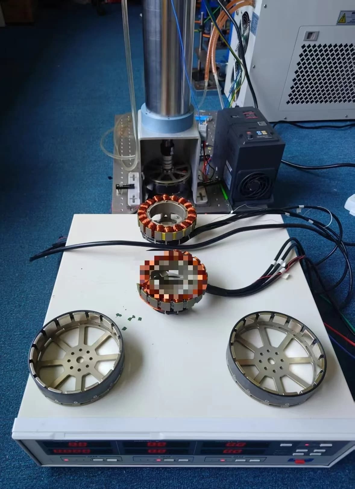
Circular motor assemblies and test fixture on bench, with central sample areas remaining pixelated

Prototype setup; sample details obscured.

Owner-provided prototype setup photograph; sample pixelation retained.

Keep predictions, sample results and the released revision connected

Agree which calculations or simulations answer the design questions, who performs them and the assumptions to record. Use prototype measurements under the agreed duty, drive and cooling conditions to review the selected revision.

Before pilot release, bring the accepted drawing and bill of materials together with the process/tooling documents, inspection and test plan, sample records and change authority.

Define the development, tooling, sample and test scope separately from the production quotation. Share target quantities and dates so the estimate reflects the actual work and dependencies.

Custom motor development questions

What do you need to start a custom motor project?

Share the duty, available space, supply and drive, interfaces and project stage. Include a drawing or current motor specification where available. Identify unknowns so the first review can focus on the decisions that affect the design.

Can we start with a stator and rotor set rather than a housed motor?

Yes. Start with the active-part envelope and define how your machine supports the rotor, retains the parts, controls the air gap and removes heat. Agree the sensing and electrical interfaces and the assembly work to include in the development scope.

Can you evaluate an alternative to our current motor?

Bring the reference data and explain what must stay the same. Compare the mechanical, electrical, thermal and operating requirements, then agree the prototype tests that will establish suitability for your application. A model number or datasheet is enough to start identifying the missing information.

Can we request winding or mechanical interface changes?

Include the requested change and its purpose in the brief. The review connects winding and supply requirements with the torque-speed duty, and mechanical changes with the mounting and load path before the prototype scope is agreed.

How are design or simulation results checked?

Define the questions, assumptions and expected outputs first. Keep predicted values separate from measured results, and use the prototype test plan to assess the selected revision under the agreed conditions.

How long will development take and what does it cost?

The estimate follows the design, tooling, prototype and test scope. Share target dates and quantities so the plan can identify engineering work, dependencies and the proposed iteration schedule.

What is needed before pilot production?

Agree the accepted revision, tests and inspection records, process/tooling documentation, planned quantity and production arrangements. Use those records to control the handoff from the prototype to the pilot build.

How should we send drawings or motor reference files?

Start with the web brief, then email drawings or motor reference files to [email protected] using your project reference. The enquiry form does not provide file upload.

References for the development brief

Continue the design decision

Application & assembly review

Turn Your Motor Requirement Into a Prototype Plan

Send the operating cycle, available space and fixed interfaces. Include your current motor reference or stator-rotor scope, and identify the design questions you want the first prototype to resolve.

Bring a sketch, selected components or the open interface questions. Use the review to define the assembly scope and next development step.