EO/IR tracking · Inspection cameras · Optical instruments
Pan-tilt actuator integration for optical tracking
Connect the payload, drive, bearings and feedback before selecting the actuator. Magatom helps OEM teams develop a pan-tilt assembly brief for optical tracking and inspection, then plan the interfaces and prototype evaluation together.
Magatom Dynamics · Application engineering guide · Reviewed
Start with the mechanism and its assembly boundary
A camera or optical payload brings more than a mass figure to an axis. Its centre of gravity, inertia, cable path and mounting datums shape the drive requirement. A slowly scanning platform, a rapid reversing inspection head and a continuously rotating instrument can need different transmission, feedback and support arrangements.
Start with what the payload must do over time. Separate acceleration, steady motion, dwell and reversal, and identify the reference at which position is evaluated. This connects the motor choice to the output structure and gives the mechanical, electrical and controls teams a common assembly boundary.
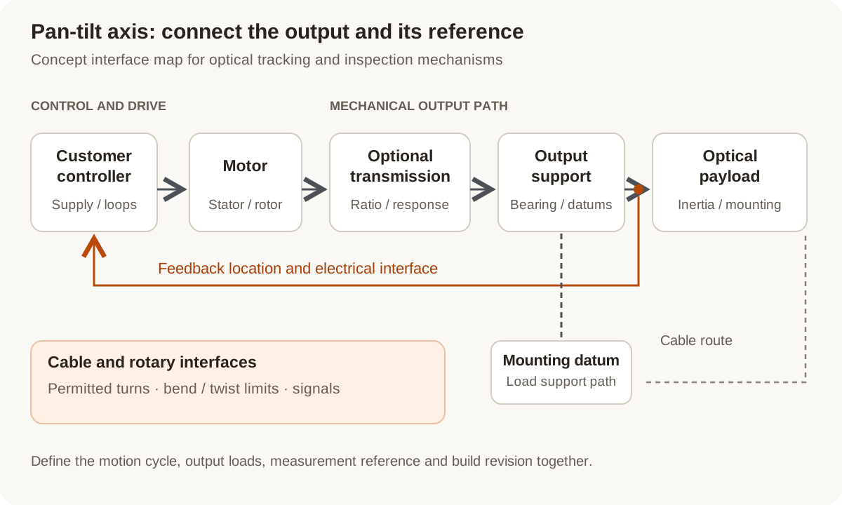
Concept interface map: review the drive chain, payload support and feedback reference together. The cable path is a separate packaging decision.
Original Magatom application-engineering diagram. Scroll horizontally to inspect the diagram labels.
Compare drive architectures at the optical payload
Use the required output cycle and package to compare these starting points. The architecture choice establishes which interfaces need drawings and which operating points need evaluation.
| Architecture | When to compare | Interfaces to review |
|---|---|---|
| Direct-drive axis | Compare when the motor can be sized and packaged around the required output torque and speed without a reduction stage. | Define the output bearing, motor thermal path, rotor/payload mounting and feedback arrangement. Include holding and disturbance loads in the brief. |
| Motor and reduction stage | Compare when the motor operating range, output torque and installation envelope favor a geared arrangement. | Review the actual ratio, torque-speed cycle, stiffness and reversal behavior of the selected configuration. Include couplings and output support rather than reviewing the gear alone. |
| Integrated actuator baseline | Start with a documented actuator when its envelope and published operating points are useful comparison inputs. | Check mounting, output loads, feedback access, cabling and controls against the axis. List the adaptations and acceptance work needed for the requested build. |
Keep the positioning metrics and measurement locations distinct
A useful axis specification names the quantity, reference, load state and test conditions. The following distinctions help turn a general request for precision into an evaluation plan.
Resolution, accuracy and repeatability
An encoder step size, closeness to a reference angle and return-to-position behavior describe different things. Write separate targets rather than converting an encoder count into an assembled-axis accuracy claim.
Backlash and low-torque lost motion
Tooth clearance and torsional response around a load reversal are different gear characteristics. Read the selected gear data and its measurement conditions; a zero-backlash description does not eliminate the need to evaluate the complete axis.
Feedback reference and structural load path
Record where position is sensed relative to the transmission, bearing and payload. Decide what the system must observe at that location and what movement or deflection remains between it and the optical reference.
Cable travel and continuous rotation
Define the permitted turns, bend or twist behavior, connector space and required signals. Compare a limited-travel cable arrangement with a rotary electrical interface only when the motion and signal requirements call for it.
Prepare the load, environment and interface brief
Send the values you know and identify the open choices. These are application inputs for review; keep the requested targets separate from the specifications of any selected component.
| Input | What to send | Decision it supports |
|---|---|---|
| Payload and orientation | Mass, centre of gravity, inertia about each axis and mounting orientation. | Connects the optical package to torque, bearing and structural requirements. |
| Motion cycle | Travel, speed, acceleration, reversal, dwell and cycle repetition. | Separates short moves and peaks from the continuing thermal and load duty. |
| Positioning targets | Pointing accuracy, repeatability, settling or stability, each with a reference and conditions. | Defines what must be measured rather than relying on one precision label. |
| External and support loads | Payload offsets, axial/radial loads, moments and specified disturbances. | Makes the output bearing and its mounting part of the assembly review. |
| Mechanical interfaces | Envelope, datums, pilot features, bolt pattern and mating drawings. | Establishes the motor/transmission/payload mounting boundary. |
| Feedback and controls | Sensor location, supply, signals, controller interfaces and position retention needs. | Identifies electrical and controls work alongside the mechanical build. |
| Cable and rotary interfaces | Permitted turns, cable bundle, signal types, connector space and routing. | Distinguishes a limited-angle arrangement from continuous-rotation packaging. |
| Environment and project stage | Exposure and thermal targets, prototype quantity, planned tests and production stage. | Sets the configuration and evaluation scope for the next revision. |
Plan the prototype observations and next revision
01
Freeze the interface revision
Review mounting datums, the output support, feedback location and cable sweep against the selected architecture.
Planned output: A common interface drawing and a list of open mechanical/electrical decisions.
02
Evaluate the representative load cycle
Agree the payload or fixture, motion sequence, power/thermal conditions and measurement reference before running the prototype.
Planned output: Configuration-linked motion, reversal, settling and thermal observations for the agreed conditions.
03
Review the next build and production handoff
Compare observations with the agreed targets, record changes and define the acceptance records required for the next build.
Planned output: A revision decision, updated assembly brief and pilot/production planning inputs.
Shape the assembly-development scope
- A requirement and architecture comparison covering motor, transmission, support and feedback interfaces.
- An agreed prototype revision with measurement references, load conditions and acceptance questions.
- A development and production plan identifying the build scope, performing parties and documentation.
Questions about pan-tilt actuator integration
Should a pan-tilt axis use direct drive or a gearbox?
Compare the required output cycle, available motor envelope, support loads and thermal path. A reduction stage changes the motor operating point and introduces additional interfaces. The useful choice follows the complete axis brief and the prototype evaluation conditions.
Where should the position feedback be measured?
Specify the reference the controller and acceptance test need to observe. Then locate feedback relative to the transmission, bearing and payload. Review the interfaces between that location and the optical reference before choosing a sensing arrangement.
Does finer encoder resolution establish pointing accuracy?
Resolution describes an output step, while accuracy concerns agreement with a reference. Repeatability is another measure. Define the assembled-axis target and test reference separately from the encoder specification.
Does every pan-tilt mechanism need a slip ring?
Start with the rotation range and cable constraints. A limited-angle mechanism may use a managed cable route. Continuous rotation can require a rotary interface, selected around the actual power, signals, space and operating cycle.
Can we start from one of the fourteen catalogue actuators?
Use the published torque, speed, ratio, dimensions and documented interfaces as comparison inputs. Then identify the configuration, mounting, feedback, control and evaluation requirements for your axis. The catalogue remains tied to its listed operating conditions.
What is enough information for the first discussion?
Send the payload and motion cycle, a sketch or envelope, the output mounting and feedback requirements, and your current development stage. Mark open choices clearly so the first review can concentrate on the interfaces and prototype decisions that need work.
Connect the brief to component and project information
Technical reading behind the interface decisions
- Renishaw: Optical encoder frequently asked questions
Resolution, repeatability and accuracy definitions.
- Harmonic Drive: Harmonic Drive engineering catalogue
Engineering-data glossary, printed pages 356–357 (PDF page 179): lost motion and hysteresis definitions.
Application & assembly review
Define the next pan-tilt assembly revision
Share the payload, motion cycle, mounting envelope, feedback reference and cable requirements. Bring your selected components or an open architecture for comparison.
Bring a sketch, selected components or the open interface questions. Use the review to define the assembly scope and next development step.