ROV mechanisms · Submerged inspection · Rotary and linear motion
Subsea actuator integration
Develop the drive and pressure boundary together. Magatom helps OEM teams define the output, housing, cable and magnetic interfaces of submerged inspection and ROV mechanisms.
Magatom Dynamics · Application engineering guide · Reviewed
Start with the mechanism and its assembly boundary
An ROV thruster, a camera-tilt axis, a manipulator joint and a valve mechanism do different work. Begin with the motion output: propulsion thrust, controlled rotation, linear travel or holding. That choice sets the load description and helps separate the mechanism from the vehicle, tether and higher-level controller.
Then draw the pressure boundary. A dry housing, a pressure-balanced oil-filled arrangement and a purpose-designed flooded motor expose different components to the surrounding fluid or pressure. Depth, immersion duration, temperature, cycling and service access belong in the same brief as the motor and transmission.
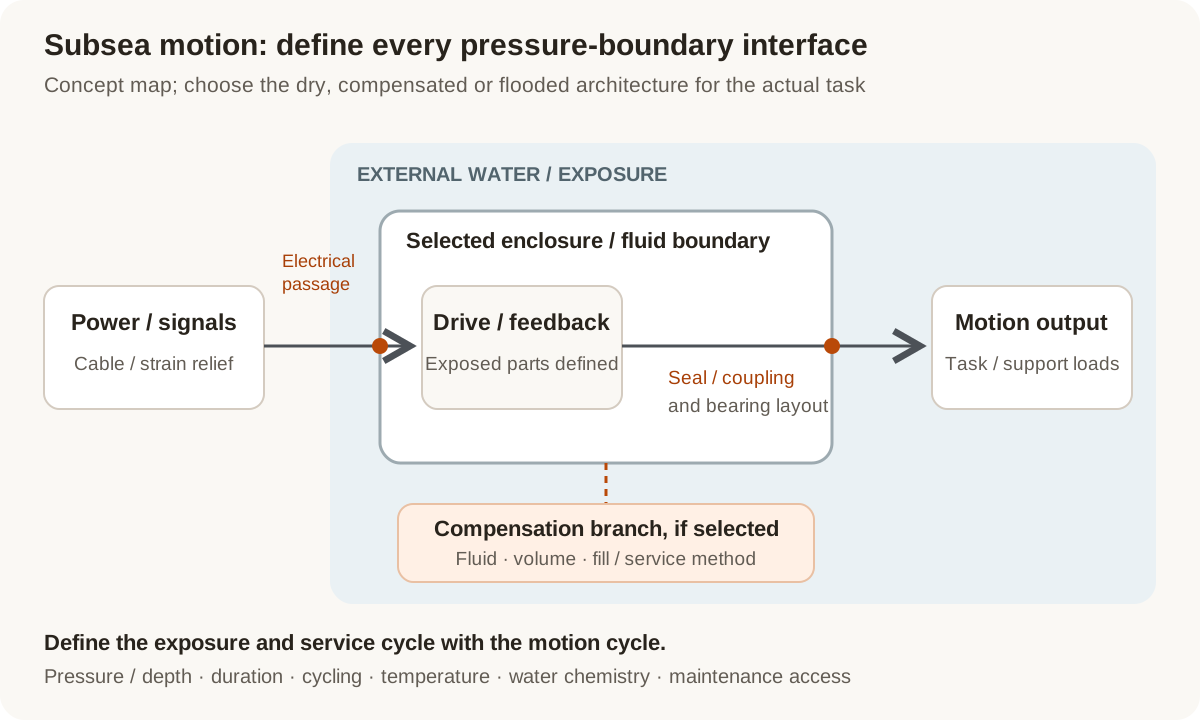
Concept pressure-boundary map: define the chosen housing arrangement, motion output and electrical passage together. Compensation is an architecture choice, not a depth rating.
Original Magatom application-engineering diagram. Scroll horizontally to inspect the diagram labels.
Compare which components see water, oil and pressure
These starting points organize a review; the detailed boundary and component choices follow the actual motion and exposure requirements.
| Architecture | When to compare | Interfaces to review |
|---|---|---|
| Dry housing with a motion output | Compare when selected drive and feedback components are intended to remain inside a dry pressure enclosure. | Review housing loads, output sealing or isolated coupling, bearings, cable penetrations and access. Identify the differential pressure at each boundary. |
| Oil-filled, pressure-compensated arrangement | Compare when the selected components and mechanism can be designed for a compatible fluid-filled pressure arrangement. | Define the fluid, compensator function, displaced volume, seals, electrical compatibility and fill/service method for the complete configuration. |
| Purpose-designed flooded motor | Compare for a task whose motor and wetted components are designed to operate with surrounding water, such as a documented thruster architecture. | Review the actual wetted construction, bearings, corrosion, electrical isolation and task-specific output. Keep propulsion requirements separate from positioning loads. |
Review the output and electrical passages as pressure interfaces
A useful subsea assembly definition identifies both the load path and every passage through the selected boundary. Material and enclosure decisions follow that complete arrangement.
Depth, duration and pressure cycling
State the pressure or depth reference, immersion duration, temperature and number of exposure cycles. Distinguish normal operation, storage and recovery. Record differential pressure and the operating sequence needed for an agreed evaluation.
Output support, sealing and coupling
Connect output torque or thrust, speed, side loads and travel to the bearing and mounting arrangement. Compare a shaft/rod passage with an isolated coupling where relevant. A magnetic coupling changes the interface to review; it does not close the housing or complete an assembly qualification by itself.
Cables, penetrators and feedback
Define the cable construction, connector or penetrator, strain relief, power and feedback signals. Identify where position is measured and which parts contact water or fill fluid. Review the passage and the connected components as a configuration.
Fluid, corrosion and maintenance
Record water chemistry, contamination, exposed material combinations and required service intervals. Include fluid compatibility for a filled arrangement and access for cleaning, seals, filling or replacement. Installation and maintenance assumptions belong in the assembly brief.
Prepare the load, environment and interface brief
Send the values you know and identify the open choices. These are application inputs for review; keep the requested targets separate from the specifications of any selected component.
| Input | What to send | Decision it supports |
|---|---|---|
| Motion task | Propulsion, rotation, linear travel or valve function; required cycle and holding state. | Defines the correct output and system boundary. |
| Output loads | Torque/thrust, speed, travel, bearing loads and mating geometry. | Connects the drive to the mechanism and external support. |
| Pressure and exposure | Depth/pressure reference, immersion duration, cycling and temperature. | Defines exposure cases rather than a single waterproof label. |
| Boundary architecture | Dry, compensated or flooded concept; component locations and service envelope. | Identifies which parts see differential pressure, fluid or water. |
| Fluid and material conditions | Water chemistry, debris, candidate fill fluid and exposed material combinations. | Sets compatibility and corrosion questions for the selected layout. |
| Electrical and feedback interfaces | Power, signals, sensor location, cables, connectors/penetrators and strain relief. | Connects the pressure boundary to the controller and measurement chain. |
| Service and recovery | Inspection access, filling/seal work, cleaning, recovery and replacement requirements. | Keeps the mechanism maintainable within the actual installation. |
| Prototype acceptance | Configuration, intended pressure/load sequence, observations, quantity and project stage. | Defines a traceable evaluation and next-build decision. |
Plan the prototype observations and next revision
01
Review the boundary and configuration
Agree the output, housing, fluid/water exposure, penetrations, materials and service interfaces before freezing the prototype revision.
Planned output: A pressure-boundary drawing, configuration list and open-interface record.
02
Agree the pressure and motion sequence
Define the exposure, dwell, pressure cycles, load/motion events and requested electrical, sealing and functional observations with the evaluation team.
Planned output: A configuration-linked test scope with observation methods and acceptance questions.
03
Review condition and the next revision
Assess the agreed observations and service findings, identify changes and define what must be re-evaluated after a boundary or component revision.
Planned output: An updated interface brief and build/acceptance requirements for the next unit.
Shape the assembly-development scope
- A motion-task and pressure-boundary comparison for the proposed mechanism.
- Defined drive, magnetic/coupling, housing, cable and feedback interfaces.
- A prototype revision and agreed exposure/function evaluation plan.
Questions about subsea actuator integration
Can one drive specification cover a thruster and an ROV joint?
Start with their different outputs. A thruster is evaluated for propulsion, while a joint needs its rotation, load support, position/feedback and holding behavior defined. Share the actual mechanism task before comparing drive or pressure arrangements.
Does IP68 specify the operating depth of a subsea actuator?
An IP label alone does not give this mechanism’s full operating brief. Request the actual immersion conditions and configuration, and define the pressure, duration, cycling, temperature and motion required for the assembly evaluation.
Does adding oil make a standard actuator pressure compensated?
A compensated arrangement needs a defined fluid and pressure/volume accommodation path, compatible components, electrical interfaces and service method. Review those features as a complete configuration rather than treating filling as a finished conversion.
Can a magnetic coupling replace every subsea shaft seal?
Compare the proposed coupling with the required load, speed, gap, barrier, support and installation geometry. It is one possible output architecture. The housing, penetrations, exposed materials and evaluation requirements still need their own definition.
Can we use our existing subsea cable and connector?
Supply the exact parts, cable construction, interface drawings, electrical signals, strain relief and documented exposure conditions. These can become fixed interfaces for the motor, feedback and housing review.
What information is useful before a pressure-test quote?
Identify the assembly revision, boundary, depth/pressure reference, duration, cycles, temperature and motion/load sequence. Agree the required observations and acceptance record with the evaluation team so the quoted work describes the actual configuration.
Connect the brief to component and project information
Technical reading behind the interface decisions
- Blue Robotics: T200 thruster configuration and operating specifications
An example of specifications tied to an identified underwater product.
- Tecnadyne: Subsea actuator and pressure-compensation questions
Manufacturer examples of oil-filled compensated actuators, output seals and feedback interfaces; not ratings for other assemblies.
- Blue Robotics: Watertight enclosure assembly and service guide
Documented sealing, cable/bulkhead, submersion-duration and corrosion considerations for an identified enclosure family.
- Banner Engineering: IP ratings and specified immersion conditions
Manufacturer explanation of why IP68 test depth, duration and operating conditions must be read in the product documentation.
Application & assembly review
Define the subsea motion and pressure interfaces together
Send the motion task, loads, boundary sketch, depth/exposure cycle, cables and service requirements. We can organize the component interfaces and prototype scope around your proposed mechanism.
Bring a sketch, selected components or the open interface questions. Use the review to define the assembly scope and next development step.