Mechanically steered antennas · Radar pedestals · Mobile platforms
Antenna positioning drive integration
Connect the payload, pedestal and controller before selecting the drive. Magatom helps OEM teams develop motor, support and feedback interfaces for mechanically steered antennas and radar positioners.
Magatom Dynamics · Application engineering guide · Reviewed
Start with the mechanism and its assembly boundary
Begin with the steering architecture. A moving antenna pedestal needs a defined motion chain; an electronically steered array may steer its beam without that mechanical chain. A hybrid platform can contain both. Identify the part that physically moves and the axis work your team wants to develop.
For a mechanical pedestal, the useful brief describes the antenna, its support structure and the platform beneath it. Separate normal tracking, acquisition, repositioning and parked states. The drive must be reviewed with the loads, required motion and measurement reference in each state, rather than selected from payload mass alone.
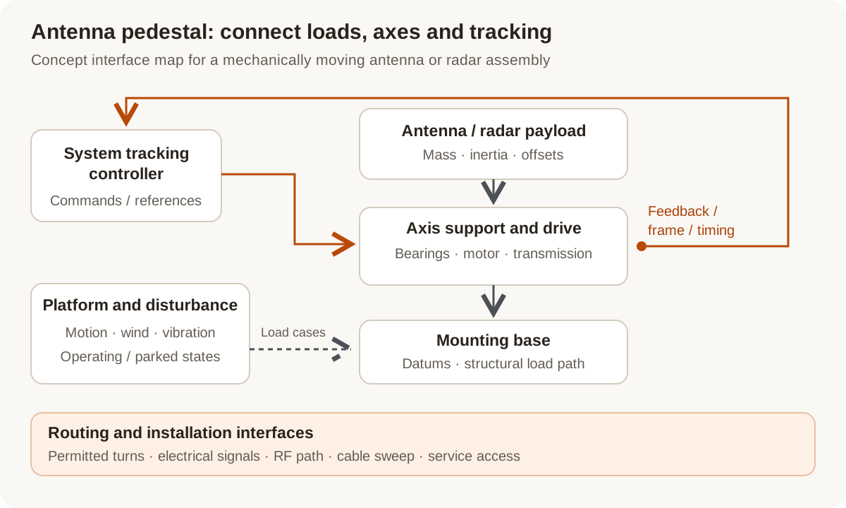
Concept pedestal map: connect antenna loads and platform disturbances to the support and drive, then define the feedback and higher-level tracking interfaces.
Original Magatom application-engineering diagram. Scroll horizontally to inspect the diagram labels.
Define which part of the tracking system moves
The system architecture determines whether there is a pedestal-drive task and where its boundary lies. Compare these layouts before specifying a motor or gear ratio.
| Architecture | When to compare | Interfaces to review |
|---|---|---|
| Mechanically steered pedestal | Compare when physical azimuth, elevation or another defined axis points the antenna or radar payload. | Map the axis sequence, required travel, bearing arrangement, payload offsets, drive coupling and cable route to the mounting base. |
| Electronic beam steering | Identify when the array steers the beam electronically and no corresponding moving pedestal axis is required. | Separate any remaining deployment, adjustment or support mechanism from beam steering. Define only the mechanical work actually needed. |
| Hybrid mechanical and electronic layout | Compare when a mechanical axis changes the array orientation while electronics provide another part of the tracking function. | Assign commands, reference frames and travel limits between the mechanical drive and the system controller; identify their independent acceptance targets. |
Build the pedestal brief around load states and control boundaries
Antenna pointing is a system task. An assembly review becomes actionable when the mechanical load path and the signals crossing it are both explicit.
Tracking, acquisition and parked loads
List the motion cycle for tracking separately from acquisition moves, stow and transport. Supply wind or other disturbance load cases with direction, duration and the required operating state. A survival condition and an operating tracking target answer different questions.
Support stiffness and drive torque
Connect antenna offsets and external moments to the bearing span, base and mounting datums. Review the motor and transmission against that supported mechanism. A torque comparison alone leaves the support deflection and mounting load path unresolved.
Axis feedback and platform information
Identify which signals describe the axis and which describe the moving base or external tracking target. Record reference frames, update timing and controller responsibilities. Encoder resolution remains separate from the assembled system’s pointing performance.
Rotation, RF routing and service access
Define travel and permitted turns together with power, data and RF paths. Distinguish electrical slip-ring requirements from an RF rotary interface. Include cable sweep, connectors and access for the intended maintenance tasks in the pedestal envelope.
Prepare the load, environment and interface brief
Send the values you know and identify the open choices. These are application inputs for review; keep the requested targets separate from the specifications of any selected component.
| Input | What to send | Decision it supports |
|---|---|---|
| Steering and axis layout | Mechanical, electronic or hybrid architecture; moving axes and travel. | Identifies the physical assembly work and control boundary. |
| Payload and mounting | Mass, inertia, centre of gravity, radome/support loads and mating datums. | Connects the antenna package to the pedestal and its bearings. |
| Operating states | Tracking cycle, acquisition moves, stow, parking and transport arrangements. | Separates moving duty from holding and nonoperating load cases. |
| Platform disturbances | Base motion, vibration, wind or imposed forces with state and duration. | Defines the disturbance inputs the system team wants evaluated. |
| Support and installation | Bearing envelope, overturning moments, mounting stiffness and available space. | Makes the structural support part of the drive comparison. |
| Tracking and feedback interfaces | Reference frames, position signals, platform inputs, controller interfaces and timing. | Assigns signal and control responsibilities between assemblies. |
| Cable and RF paths | Permitted turns, power/data/RF routing, connector space and service access. | Defines routing interfaces that may constrain the axis layout. |
| Evaluation and delivery stage | Pointing/settling targets and reference, environment, prototype quantity and build stage. | Creates a configuration-linked prototype and acceptance brief. |
Plan the prototype observations and next revision
01
Review the pedestal load path
Agree the mounting reference, supported payload, bearing layout and operating/parked load cases with the system team.
Planned output: A mechanical interface revision and separate load cases for drive and support review.
02
Define the motion and signal trial
Specify representative tracking/acquisition sequences, supplied platform signals and the measurement reference before evaluating a prototype.
Planned output: An agreed observation plan for travel, reversal, settling and control interfaces.
03
Close the installation interfaces
Review cable/RF sweep, connectors, service access and required acceptance records against the next assembly revision.
Planned output: An updated pedestal brief and prototype-to-production handoff inputs.
Shape the assembly-development scope
- A comparison of drive, transmission and support arrangements for the actual moving axes.
- Defined mechanical, feedback and higher-level control interfaces with open decisions identified.
- A prototype revision and agreed evaluation scope tied to the platform and load states.
Questions about antenna positioning drives
Does every SOTM terminal need a motor-driven pedestal?
No. First identify mechanical, electronic or hybrid steering. This guide addresses the physical axes and interfaces of a mechanically moving assembly. An electronically steered beam does not by itself create that same drive requirement.
Can the motor be sized from antenna mass alone?
Include inertia, centre of gravity, motion, support loads and external disturbances. Also identify the operating state. The same payload can produce different drive and bearing requirements during tracking, stow and transport.
How should tracking and survival conditions be specified?
Record them as separate load cases. State the imposed conditions, duration and expected system behavior for each. This keeps an operating pointing target separate from the mechanical conditions of a parked or transported assembly.
Are the axis encoder and platform motion signals interchangeable?
They describe different references. Map each signal’s location, frame, timing and receiving controller. Then define how the system uses those signals and where the assembled-axis behavior will be measured.
Can a standard electrical slip ring carry the required RF path?
Specify power, data and RF interfaces separately. The RF frequency path, permitted rotation, signal requirements and available space determine the appropriate rotary-interface review. Do not assign that function from an electrical slip-ring label alone.
What should we send for a pedestal integration discussion?
Send the steering layout, payload and motion cycle, platform/load cases, mounting envelope, feedback/control interfaces and cable/RF routing. Include selected components and the project stage so the review can focus on the assembly work still open.
Connect the brief to component and project information
Technical reading behind the interface decisions
- Orbit Communication Systems: OceanTRx 4 stabilized antenna system description
A documented mechanical pedestal with axis travel, platform-motion and gyro-interface specifications. Ratings belong to that antenna system.
- Gilat: Electronically steered antenna architecture
Electronic beam steering as a distinct system architecture from a moving mechanical pedestal.
- Renishaw: Optical encoder frequently asked questions
Resolution, repeatability and accuracy definitions.
Application & assembly review
Connect the antenna, pedestal and control requirements
Share the moving-axis layout, payload, disturbance inputs, support envelope and control/RF boundaries. We can organize the drive interfaces and the next prototype decisions around that brief.
Bring a sketch, selected components or the open interface questions. Use the review to define the assembly scope and next development step.