Thrust stands · Structural loads · Ground testing
Thrust stand and load-test interfaces
Connect the fixture and measurement chain before selecting the hardware. Magatom helps OEM teams define load paths, sensor mounts, cable interfaces and evaluation inputs for ground test assemblies.
Magatom Dynamics · Application engineering guide · Reviewed
Start with the mechanism and its assembly boundary
Define what the ground test needs to measure: an axial force, several forces and moments, or reactions at a set of supports. Specify the test article, coordinate system, load cases and required observations. This establishes the fixture and sensing boundary before choosing a transducer or acquisition interface.
Follow the force from the test article through adapters, the selected sensing arrangement and the supporting structure. Include restraints, cables, hoses and other connections that can affect the measured reaction. The fixture and the measurement chain need a common interface brief, whether the customer already owns the sensor and DAQ or is still comparing them.
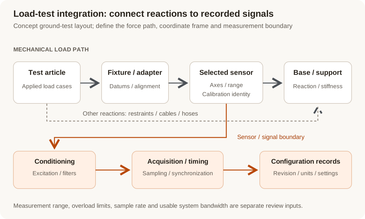
Concept fixture and measurement-chain map: review the intended load path, additional reactions, sensor interfaces and acquisition boundary together. No measured force trace or calibrated test result is depicted.
Original Magatom application-engineering diagram. Scroll horizontally to inspect the diagram labels.
Choose the sensing layout from the required load components
Compare layouts around the coordinate frame, expected loads and support arrangement. A larger channel count is useful only when its mounting and measurement role are defined.
| Architecture | When to compare | Interfaces to review |
|---|---|---|
| Single-axis force path | Compare when a defined axial reaction is the primary observation and the fixture can support the other required constraints appropriately. | Define the sensor axis, adapters, other supports, offsets and unintended side loads. Identify what reaction the chosen load path actually measures. |
| Multi-axis transducer interface | Compare when forces and moments at a defined mounting interface are part of the required result. | Review all load components together, coordinate frames, moment arms, mounting stiffness, calibration range and interface electronics. |
| Distributed reaction measurement | Compare when reactions at several supports form the required measurement layout. | Define sensor locations, force directions, structural constraints and how the channels are combined. Review channel calibration, timing and reference frames as part of the setup. |
Close the fixture and measurement-chain decisions together
The useful review connects the physical reactions to the recorded signals. These decisions help mechanical and instrumentation teams agree what a proposed setup can observe.
Intended and additional reaction paths
Map the test article, adapters, sensor, base and every restraint or cable/hose connection. Identify loads that can bypass or preload the sensing path. Include thermal movement, alignment and the reference frame when reviewing the mounted fixture.
Range, combined loads and overload provisions
Record expected force/moment combinations and dynamic peaks against the chosen calibration and overload limits. If a stop or restraint is proposed, identify when it engages and whether it creates an additional reaction path. Measurement range and damage limits serve different purposes.
Sensor identity and calibration records
Identify the exact sensor, interface electronics, calibration range, units and files needed for the project. Review axes, offsets, conditioning and any required traceability documentation. An axis count alone does not establish crosstalk or the uncertainty of the mounted setup.
Dynamic response and acquisition timing
Specify the event duration and frequency content of interest with the fixture/sensor response, conditioning and filters. Define per-channel sampling, synchronization, triggers and latency. A high output data rate does not by itself establish the usable bandwidth of the complete measurement chain.
Prepare the load, environment and interface brief
Send the values you know and identify the open choices. These are application inputs for review; keep the requested targets separate from the specifications of any selected component.
| Input | What to send | Decision it supports |
|---|---|---|
| Test objective and coordinates | Test article, required force/moment components, reference frame and intended observations. | Defines what the fixture and sensing layout must observe. |
| Applied load cases | Steady, combined and dynamic loads, moment arms, duration and imposed motion. | Connects measurement range and overload review to real cases. |
| Mechanical load path | Article, adapter, sensor, base, supports, restraints and cable/hose connections. | Identifies intended reactions and additional paths through the setup. |
| Sensor and mounting | Selected sensor or open choices, mounting drawings, axes, datums and available envelope. | Defines the physical interface and configuration to review. |
| Calibration and documentation | Sensor/interface identities, calibration range/files, units and required traceability records. | Makes the measurement evidence and configuration explicit. |
| Signal and acquisition chain | Excitation, conditioning, filters, channels, sample rates, timing and trigger interfaces. | Connects the selected sensor to the recorded data. |
| Dynamic and environmental conditions | Frequency content, event duration, mounting behavior, temperatures and cable conditions. | Defines observations needed beyond a static force comparison. |
| Prototype and acceptance scope | Fixture revision, planned load checks, responsible evaluation work, quantity and project stage. | Turns the brief into an agreed build and evaluation plan. |
Plan the prototype observations and next revision
01
Review the fixture and reference frame
Agree the load cases, mechanical path, sensor/support datums, additional connections and the measurement coordinates.
Planned output: A fixture/interface revision and a list of reactions and channels to observe.
02
Define the measurement-chain checks
Agree sensor/interface identities, records, conditioning and acquisition settings, plus a method and responsible party for checks under defined loads.
Planned output: A configuration-linked evaluation brief separating calibration information from mounted-setup observations.
03
Review dynamic observations and revisions
Compare the required event/frequency observations and mounting/cable behavior, then identify changes and the checks needed for the next setup.
Planned output: An updated fixture revision and test-team acceptance inputs for repeat builds.
Shape the assembly-development scope
- A fixture and adapter brief around the actual article, sensor and supporting structure.
- Defined mechanical, cable, conditioning and acquisition interfaces with selected parts identified.
- A prototype revision and agreed configuration/evaluation documentation for the test team.
Questions about thrust stand and load-test fixtures
Should a thrust stand measure one axis or several forces and moments?
Start with the required observations and load cases. A single axial reaction, a multi-axis interface and a distributed support layout answer different questions. Define the coordinate frame, constraints and mounting before selecting the sensing arrangement.
Does a higher DAQ sample rate establish the stand’s bandwidth?
No. Review the mechanical and sensor response, conditioning/filter behavior, timing and frequency content of the event. Select sampling around that measurement chain rather than treating one data-rate number as the complete dynamic specification.
Why include cables, hoses and restraints in the fixture drawing?
They can add reactions, preload or alternative load paths. Their routing, attachment and movement help define what force the selected sensing path measures. Include them when reviewing alignment, offsets and thermal movement.
Is overload capacity the same as the calibrated measuring range?
They are distinct specifications. Compare the expected load combinations with the chosen calibration range and the selected equipment’s overload limits. Define the role and engagement of stops or restraints separately.
Can we retain our existing sensor and acquisition hardware?
Yes. Send the exact sensor/interface identities, calibration information, mounting drawings, conditioning, signals and timing requirements. The project can focus on adapters, fixtures, cable interfaces and the integration work around those parts.
What records belong with the first fixture prototype?
Record its revision, load path, axes, selected sensing/conditioning parts, calibration information and acquisition settings. Agree the observations and responsible evaluation work for the planned loads so subsequent changes can be assessed against the same reference.
Connect the brief to component and project information
Technical reading behind the interface decisions
- ATI Industrial Automation: Force/torque sensor questions and measurement definitions
Crosstalk, sensing specifications and measurement-chain considerations.
- NI: Measuring load with bridge-based sensors
Load-cell selection and the excitation, conditioning and acquisition interfaces around an actual sensor.
- NI: Analog acquisition: bandwidth, sampling and aliasing
Signal bandwidth and sample rate are distinct parts of acquisition design; no universal test-stand bandwidth is inferred.
Application & assembly review
Bring the load path and measurement interfaces into one brief
Share the test objective, load cases, fixture sketch, selected sensor/DAQ and required records. We can define the adapter and assembly interfaces needed for the next ground-test setup.
Bring a sketch, selected components or the open interface questions. Use the review to define the assembly scope and next development step.