01 · Screen the duty
Match torque and speed over time
Compare rated and peak values with the actual motion profile, including peak duration, repetition, acceleration, and thermal conditions. Do not size from peak torque alone.
Integrated planetary rotary actuator · Model 1 highlights
Size the axis around rated duty as well as peak load. At 18:1, Model 1 lists 80 Nm rated torque and 400 Nm under “Peak torque (>3 s)”; Model 2 lists 54 Nm and 250 Nm. Both list 2,220 g mass. The standard configuration has no through-bore and does not support a brake.
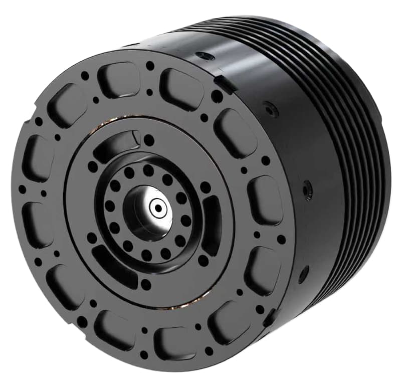
Model 1 summary
These highlights describe Model 1. Compare the configuration tables below with the load cycle, mounting and controller requirements.
Start with the listed planetary configuration and its model-specific options. Describe the interface or function that needs to change so the build, drawing and applicable limits can be reviewed together.
Describe the interface or function you would like to adjust, along with the application requirements. We can check whether a listed option or another configuration is available for this model. The exact build, drawing, and applicable limits need confirmation before an order.
Compare the listed configurations independently and specify the configuration required for quotation. Numerical highlights above describe Model 1. Unspecified cells are marked “Not specified.”
| Parameter | Unit | Model 1 | Model 2 |
|---|---|---|---|
| Operating voltage | V | 12-72 | 12-72 |
| Rated voltage | V | 48 | 48 |
| Rated torque | Nm | 80 | 54 |
| Rated speed | RPM | 50 | 90 |
| Rated current | A(rms) | 20 | 20 |
| Peak torque (>3 s) | Nm | 400 | 250 |
| Peak speed | RPM | 80 | 133 |
| Peak current | A(rms) | 100 | 100 |
| Torque constant | Nm/A | 4.17 | 2.72 |
| Back-EMF constant | Vrms/Krpm | Not specified | Not specified |
| Speed constant | rpm/V | 27 | 50 |
| Motor constant | Nm/√W | Not specified | Not specified |
| Electromechanical time constant | ms | Not specified | Not specified |
| Electrical time constant | ms | Not specified | Not specified |
| Pole pairs | — | 14 | 14 |
| Winding connection | — | Star | Delta |
| Phase resistance | Ω | 0.21 | 0.16 |
| Phase inductance | mH | 0.477 | 0.165 |
| Parameter | Unit | Model 1 | Model 2 |
|---|---|---|---|
| Reduction ratio | — | 18 | 18 |
| Reducer backlash | Arcmin | 10 | 10 |
| Output bearing | — | Crossed-roller bearing | Crossed-roller bearing |
| Backdrive torque | Nm | 0.7 | 0.7 |
| Rotational inertia | g.cm² | Not specified | Not specified |
| Weight | g | 2220 | 2220 |
| Axial load | kN | 5.9 | 5.9 |
| Radial load | kN | 2.6 | 2.6 |
| Parameter | Unit | Model 1 | Model 2 |
|---|---|---|---|
| Control bandwidth | Hz | 2000 | 2000 |
| Communication | — | CAN | CAN |
| Encoder type | — | Mechanical dual encoder | Mechanical dual encoder |
| Encoder resolution | bit | 14 | 14 |
| CAN interface | — | XT30(2+2)PB-M | XT30(2+2)PB-M |
| USB interface | — | SH1.0-4P | SH1.0-4P |
| Power interface | — | XT30(2+2)PB-M | XT30(2+2)PB-M |
| Control modes | — | Servo mode; Speed mode; Torque mode; Force-position hybrid mode | Servo mode; Speed mode; Torque mode; Force-position hybrid mode |
| Protection functions | — | Overvoltage protection; Overcurrent protection; Overtemperature protection | Overvoltage protection; Overcurrent protection; Overtemperature protection |
| Parameter | Unit | Model 1 | Model 2 |
|---|---|---|---|
| Duty type | — | S2 | S2 |
| Ingress protection | — | IP40 | IP40 |
| Cooling method | — | IC410 | IC410 |
| Ambient operating temperature | — | -20℃~50℃ | -20℃~50℃ |
| Insulation class | — | F | F |
| Dielectric strength | — | 500V 1kHz 1A 1ms | 500V 1kHz 1A 1ms |
| Insulation resistance | — | 100MΩ 20℃ | 100MΩ 20℃ |
| Noise | — | 60dB/1.0m | 60dB/1.0m |
| Temperature sensor | — | NTC MF52B 103F3950 | NTC MF52B 103F3950 |
All data are provided for U= 48 V and T= 25°C, unless otherwise specified. Specifications for different voltage levels or other operating limits, and corresponding simulation models, are available upon request.
Send it with the duty cycle and controller requirements for a model-specific engineering review.
01 · Screen the duty
Compare rated and peak values with the actual motion profile, including peak duration, repetition, acceleration, and thermal conditions. Do not size from peak torque alone.
02 · Check interfaces
Compare the original drawing with the mating parts, loads, cable route, connectors, supply, communication protocol, and feedback requirements.
03 · Confirm the build
Confirm the selected Model 1/Model 2 configuration, current drawing revision, option content, test conditions, and validation evidence before freezing a design.
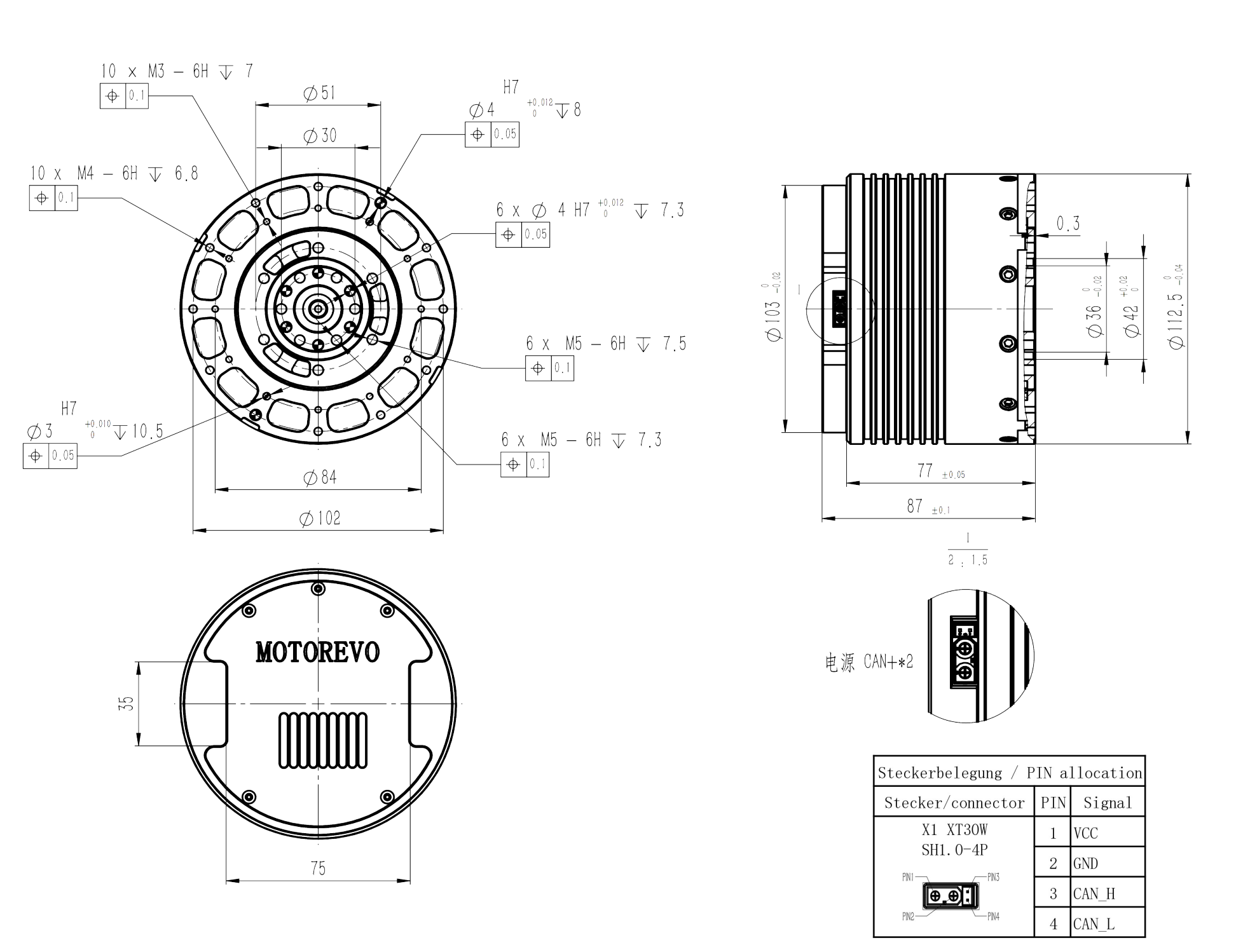
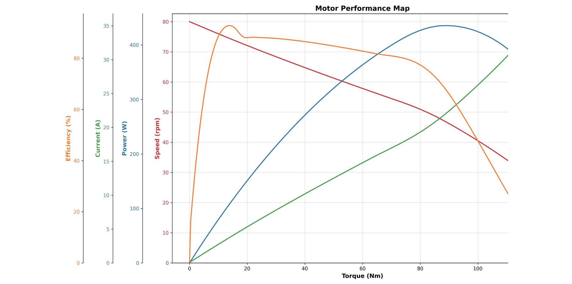
Check mounting and cable clearances in the original 2D drawing. Review the torque, speed, power, current and efficiency map with the selected configuration; confirm curve identities and test conditions before using it for controller or thermal sizing. Open either image for a larger view.
A STEP file is available for this model on request. The email includes the public SKU and asks you to identify the required configuration.
Compare the rated duty, ratio and interfaces of these related models before choosing a configuration for quotation.
Planetary · Model 1
40 Nm rated torque · 170 Nm peak torque · 10:1 ratio
Compare Model SpecificationsPlanetary · Model 1
60 Nm rated torque · 300 Nm peak torque · 18:1 ratio
Compare Model SpecificationsHarmonic · Model 1
108 Nm rated torque · 304 Nm peak torque · 100:1 ratio
Compare Model SpecificationsConnect the published specifications with your mechanism. Share the fixed interfaces and open design questions so the next review can focus on the required configuration and prototype decisions.
Use MGA-PJ-105-27-18 as the actuator reference for an output-torque sensing review. Define the sensor location, load path, bearing support, mounting and readout before selecting the combined configuration.
Keep each with its own configuration: Model 1 lists 80 Nm rated and 400 Nm under “Peak torque (>3 s),” while Model 2 lists 54 Nm and 250 Nm. Review duration, repetition and thermal conditions against the full cycle. Neither peak value is a continuous-torque rating.
Dual encoders provide motion feedback. Check their locations and interfaces for the selected configuration. A separate output-torque measurement needs its own sensor arrangement, load path and applicable calibration records. An engineered elastic element with position sensing can also measure torque; the label “dual encoder” alone does not establish that design.
Model 1 lists 14 bit encoder resolution. Resolution describes measurement increments. Installed positioning accuracy also depends on encoder performance, mounting, the transmission and control system. Use the configuration and conditions of a position test rather than interpreting a bit count as an angular-accuracy guarantee.
Use MGA-PJ-105-27-18 as the actuator reference and share the required torque measurement point, mounting drawing, operating loads and readout. Review the combined mechanical and measurement configuration as a development project, with its sensor, mounting and acceptance scope defined together.
Model 1 lists 80 Nm rated torque and 400 Nm under “Peak torque (>3 s),” with 50 RPM rated speed and 80 RPM peak speed. Check the torque-speed profile and repetition of each load against the operating conditions below. These figures are separate parameters, not a simultaneous operating point.
Compare the two listed configurations independently and specify which column is required for quotation. Match its electrical and output data to the requested drawing and performance map.
Send torque and speed over time, peak duration and repetition, acceleration, dwell and cooling conditions. Include mounting loads and the controller interface so the rated and peak values can be reviewed against the complete cycle.
Use the map to frame the torque, speed, power, current and efficiency review. Request confirmation of the curve identities, configuration and test conditions before using a curve for controller or thermal sizing.
Application & assembly review
Share the torque-speed cycle, peak duration, mounting drawing and controller requirements. Include the prototype stage, quantity range and acceptance priorities to define the next configuration review.
Bring a sketch, selected components or the open interface questions. Use the review to define the assembly scope and next development step.