
01 · Screen the duty
Match torque and speed over time
Compare rated and peak values with the actual motion profile, including peak duration, repetition, acceleration, and thermal conditions. Do not size from peak torque alone.
Planetary integrated joint actuator
The Model 1 table lists 16 Nm rated torque, 50 Nm under the source’s “Peak torque (>3 s)” label, a 36:1 ratio, and 67 rpm peak speed. The source also mentions a 100 KV version without defining its full configuration; ask for the exact winding/version data before comparing it with the listed table.
Is the listed 67 rpm peak speed suitable, or is the separately mentioned 100 KV version required?
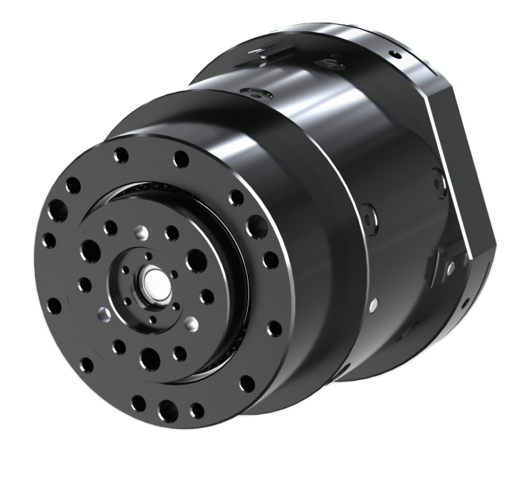
Model 1 summary
Summary values are transcribed from the catalogue strip and checked against the Model 1 table. They are not a substitute for an application duty-cycle review.
MGA-PJ-60-13-36 is identified in the supplied product literature as a planetary integrated joint actuator. The specification tables below retain the source's Model 1 and Model 2 labels and every listed field.
A catalogue value narrows the comparison. It does not establish fit for a mechanism without the load profile, mounting stack, controller, and operating environment.
The catalogue labels its columns Model 1 and Model 2 but does not define the difference between them. Both labels are retained as published. A source dash or unpopulated cell is presented as “Not specified in source.”
| Parameter | Unit | Model 1 | Model 2 |
|---|---|---|---|
| Operating voltage | V | 12-72 | Not specified in source |
| Rated voltage | V | 48 | Not specified in source |
| Rated torque | Nm | 16 | Not specified in source |
| Rated speed | RPM | 50 | Not specified in source |
| Rated current | A(rms) | 7 | Not specified in source |
| Peak torque (>3 s) | Nm | 50 | Not specified in source |
| Peak speed | RPM | 67 | Not specified in source |
| Peak current | A(rms) | 20 | Not specified in source |
| Torque constant | Nm/A | 2.29 | Not specified in source |
| Back-EMF constant | Vrms/Krpm | Not specified in source | Not specified in source |
| Speed constant | rpm/V | 50 | Not specified in source |
| Motor constant | Nm/√W | Not specified in source | Not specified in source |
| Electromechanical time constant | ms | Not specified in source | Not specified in source |
| Electrical time constant | ms | Not specified in source | Not specified in source |
| Pole pairs | — | 7 | Not specified in source |
| Winding connection | — | Star | Not specified in source |
| Phase resistance | Ω | 0.62 | Not specified in source |
| Phase inductance | mH | 0.46 | Not specified in source |
| Parameter | Unit | Model 1 | Model 2 |
|---|---|---|---|
| Reduction ratio | — | 36 | Not specified in source |
| Reducer backlash | Arcmin | 10 | Not specified in source |
| Output bearing | — | Crossed-roller bearing | Not specified in source |
| Backdrive torque | Nm | 1.3 | Not specified in source |
| Rotational inertia | g.cm² | Not specified in source | Not specified in source |
| Weight | g | 610 | Not specified in source |
| Axial load | kN | 4.8 | Not specified in source |
| Radial load | kN | 2.1 | Not specified in source |
| Parameter | Unit | Model 1 | Model 2 |
|---|---|---|---|
| Control bandwidth | Hz | 2000 | Not specified in source |
| Communication | — | CAN | Not specified in source |
| Encoder type | — | Mechanical dual encoder | Not specified in source |
| Encoder resolution | bit | 14 | Not specified in source |
| CAN interface | — | XT30(2+2)PW-M | Not specified in source |
| USB interface | — | SH1.0-4P | Not specified in source |
| Power interface | — | XT30(2+2)PW-M | Not specified in source |
| Control modes | — | Servo mode; Speed mode; Torque mode; Force-position hybrid mode | Not specified in source |
| Protection functions | — | Overvoltage protection; Overcurrent protection; Overtemperature protection | Not specified in source |
| Parameter | Unit | Model 1 | Model 2 |
|---|---|---|---|
| Duty type | — | S2 | Not specified in source |
| Ingress protection | — | IP40 | Not specified in source |
| Cooling method | — | IC410 | Not specified in source |
| Ambient operating temperature | — | -20℃~50℃ | Not specified in source |
| Insulation class | — | F | Not specified in source |
| Dielectric strength | — | 500V 1kHz 1A 1ms | Not specified in source |
| Insulation resistance | — | 100MΩ 20℃ | Not specified in source |
| Noise | — | 60dB/1.0m | Not specified in source |
| Temperature sensor | — | NTC MF52B 103F3950 | Not specified in source |
All data are provided for U= 48 V and T= 25°C, unless otherwise specified. Specifications for different voltage levels or other operating limits, and corresponding simulation models, are available upon request.
Send it with the duty cycle and controller requirements for a model-specific engineering review.
01 · Screen the duty
Compare rated and peak values with the actual motion profile, including peak duration, repetition, acceleration, and thermal conditions. Do not size from peak torque alone.
02 · Check interfaces
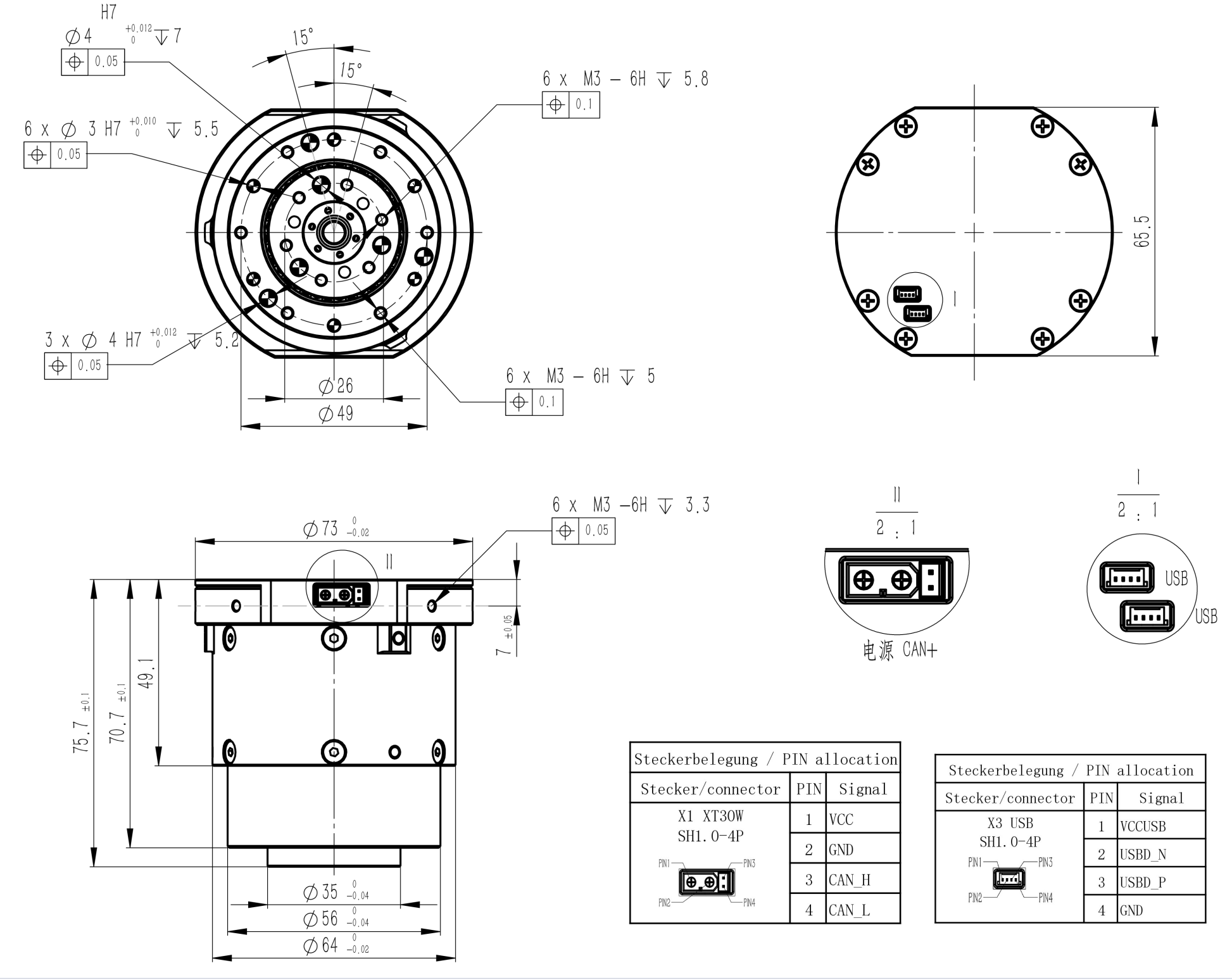
Compare the original drawing with the mating parts, loads, cable route, connectors, supply, communication protocol, and feedback requirements.
03 · Confirm the build
Confirm the selected Model 1/Model 2 configuration, current drawing revision, option content, test conditions, and validation evidence before freezing a design.
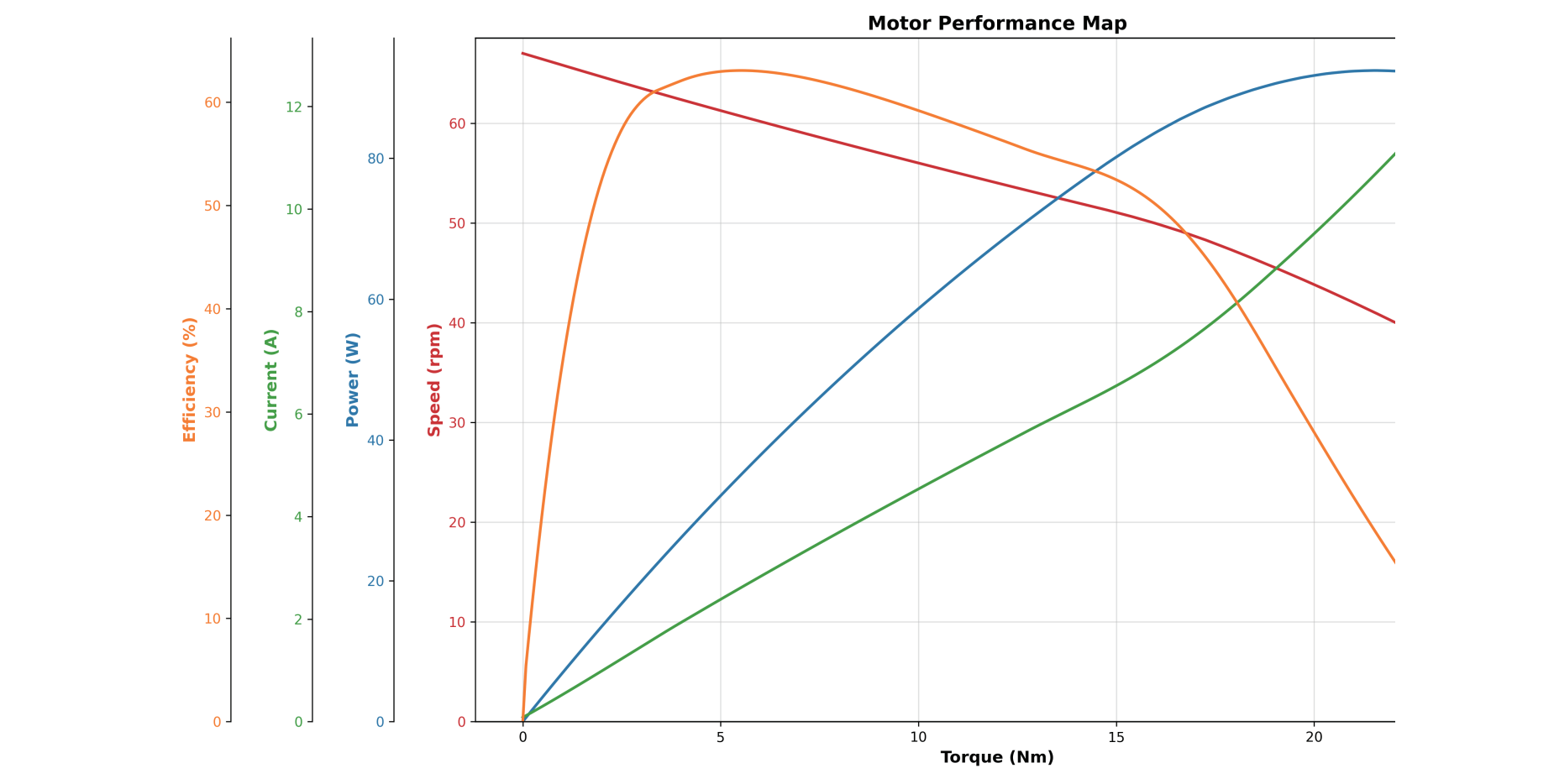
The drawing is reproduced from the supplied source image unchanged, including any visible source mark. The performance-map image is also used unchanged. Its graphic identifies torque, speed, power, current, and efficiency axes, but does not identify curve names or a Model 1/Model 2 configuration.
These links help compare published data within the same product set. Similar headline values do not make actuators interchangeable.
Planetary · Model 1
25 Nm rated torque · 76 Nm peak torque · 39:1 ratio
Compare source dataPlanetary · Model 1
27 Nm rated torque · 82 Nm peak torque · 36:1 ratio
Compare source dataPlanetary · Model 1
30 Nm rated torque · 90 Nm peak torque · 25:1 ratio
Compare source dataInclude the project inputs that let an engineer compare the source data with your mechanism. Unknown requirements can stay open; they should not be replaced with assumed operating limits.
Model 1 lists 16 Nm rated torque and 50 Nm under the source label “Peak torque (>3 s),” with 50 RPM rated speed and 67 RPM peak speed. The catalogue operating-condition note below applies unless a field is specified otherwise.
The source page populates Model 1 only. The Model 2 column is marked “Not specified in source”; this page does not infer a second configuration.
No. Use the table as a source-backed screening record. Confirm the required torque-speed profile, peak duration and repetition, duty cycle, thermal limits, mounting loads, controls, and operating environment before design release.
The supplied map shows axes for torque, speed, power, current, and efficiency but does not label the curves or identify a Model 1/Model 2 configuration. Confirm the applicable configuration and test conditions before using the map for controller or thermal sizing.
Share the torque-speed profile, peak duration, mounting drawing, power and control requirements, quantity range, and target validation. An initial review identifies missing inputs and next steps; it does not confirm performance, price, stock, or delivery timing.
An initial review identifies missing inputs and next steps. It does not by itself confirm feasibility, performance, price, or delivery timing.